Junction function
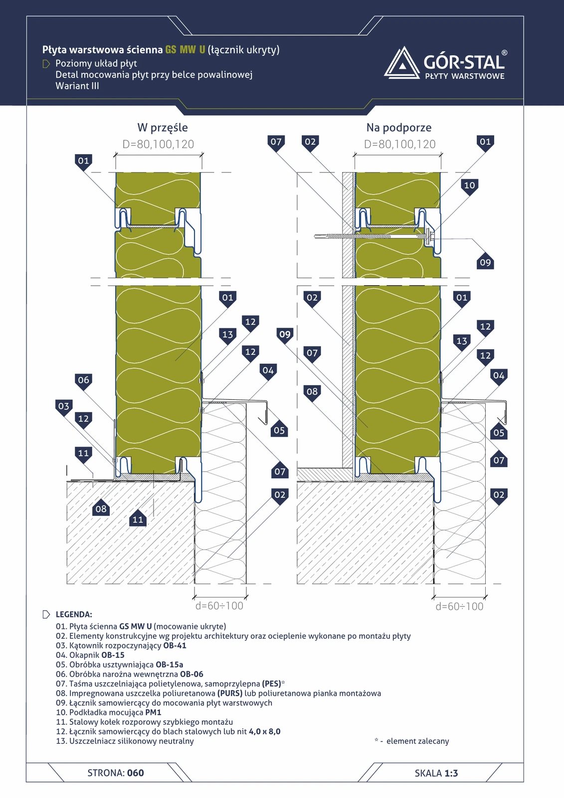
Variant III of the horizontal GS MW U plinth = OB-15 drip edge + OB-15a stiffening flashing (d=60-100 mm). The stiffest configuration among the 3 horizontal U plinth variants — OB-15a reinforces the drip edge independently of panel thickness, allowing large overhangs without the risk of deformation under wind pressure and thermal loads.
Critical installation aspects
- OB-15 + OB-15a = premium-grade drip edge with additional stiffening; L-profiled + flat sealing sheet on the external side.
- OB-41 starter angle anchored to the sill beam with steel quick-install expansion anchors — spacing ~600 mm.
- OB-06 internal corner flashing for the interior-side finish.
- PM1 concealed fixing continued up to the bottom panel row — premium aesthetics without visible fasteners.
- Drainage strip in the ground below the drip edge (gravel + geotextile); prevents water accumulation at the sill beam.
- Strength check after the first season — inspection of OB-15a stiffness + retightening of rivets joining the drip edge sheets.
Documentation
GS MW S/CH/U Technical Catalogue (Gór-Stal 2025), page 58 — Plinth, horizontal GS MW U layout, variant III. Scale 1:5.
Components in this junction
Panel (1)
- 01
Flashing (4)
- 03 OB-41 starter angle (OB-41)
- 04 OB-15 drip edge (OB-15)
- 05 OB-15a stiffening flashing (OB-15a)
- 06 OB-06 internal corner flashing (OB-06)
Accessory (1)
- 10 PM1 fixing plate (PM1)
Fastener (3)
- 09
- 11 Steel quick-install expansion anchor
- 12
Sealant (3)
- 07
- 08 Impregnated PURS gasket or expanding foam
- 13 Neutral-cure silicone sealant
Element (1)
- 02 Structural elements + insulation per design