Ridge (2)
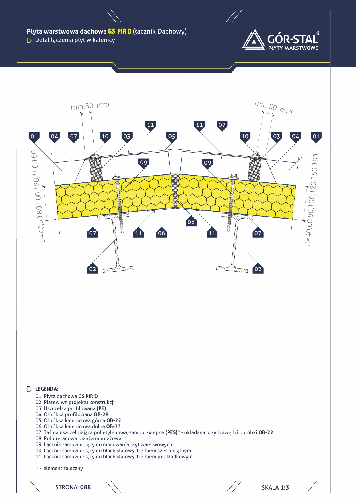
Ridge — insPIRe® D sandwich panel
Roof panel connection detail at the ridge of a dual-pitched roof. Upper OB-22 + lower OB-23 ridge flashings with PE profiled gasket between panels and flashing.
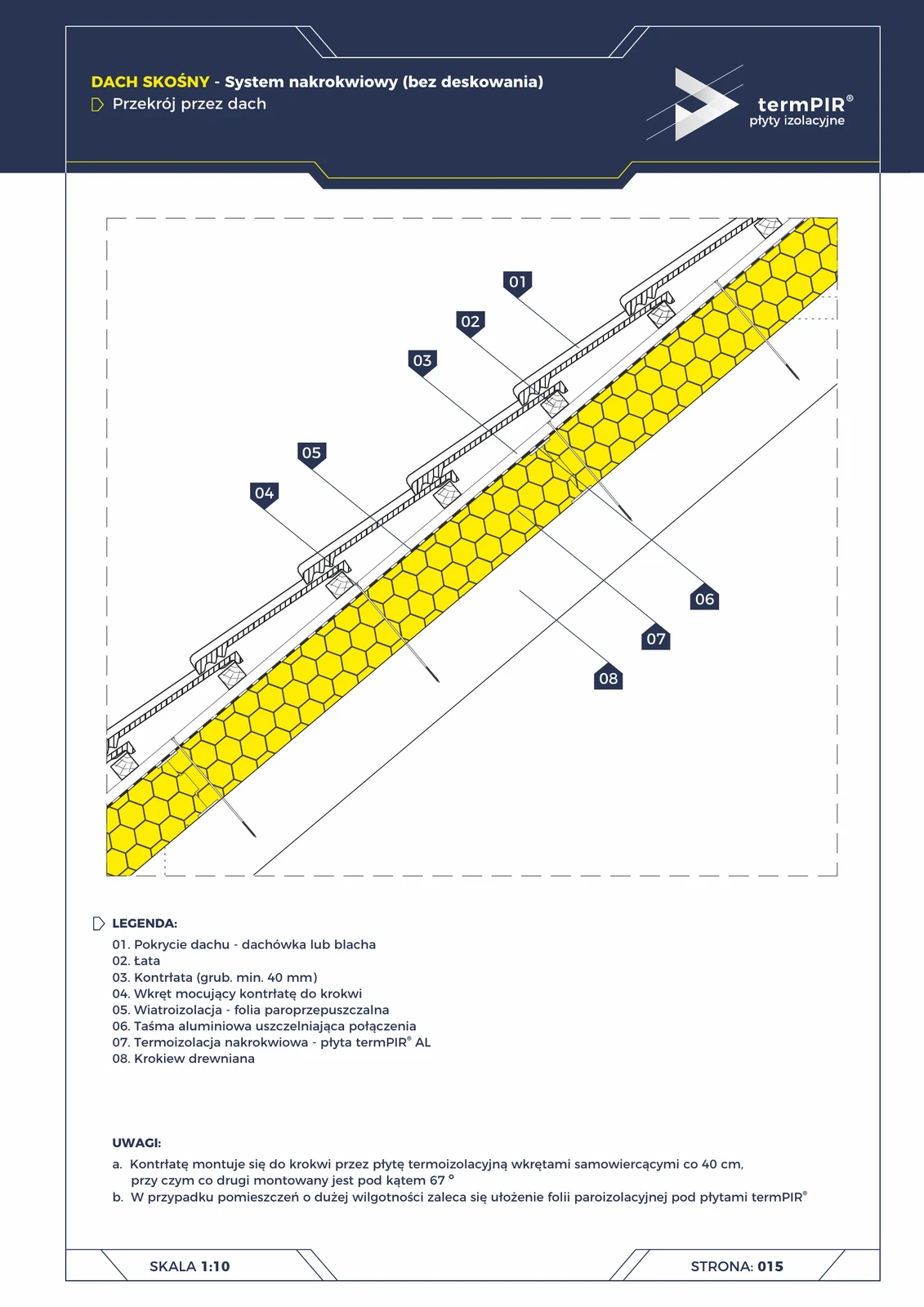
Ridge — pitched roof in the over-rafter system (termPIR® AL)
In the over-rafter system (without sheathing), the ridge requires no separate insulation flashing — termPIR® AL boards meet along the ridge line without any break in thermal continuity. Layer geometry is identical to the slope cross-section; the difference = vented ridge cap + broken counter-batten
Eaves (6)
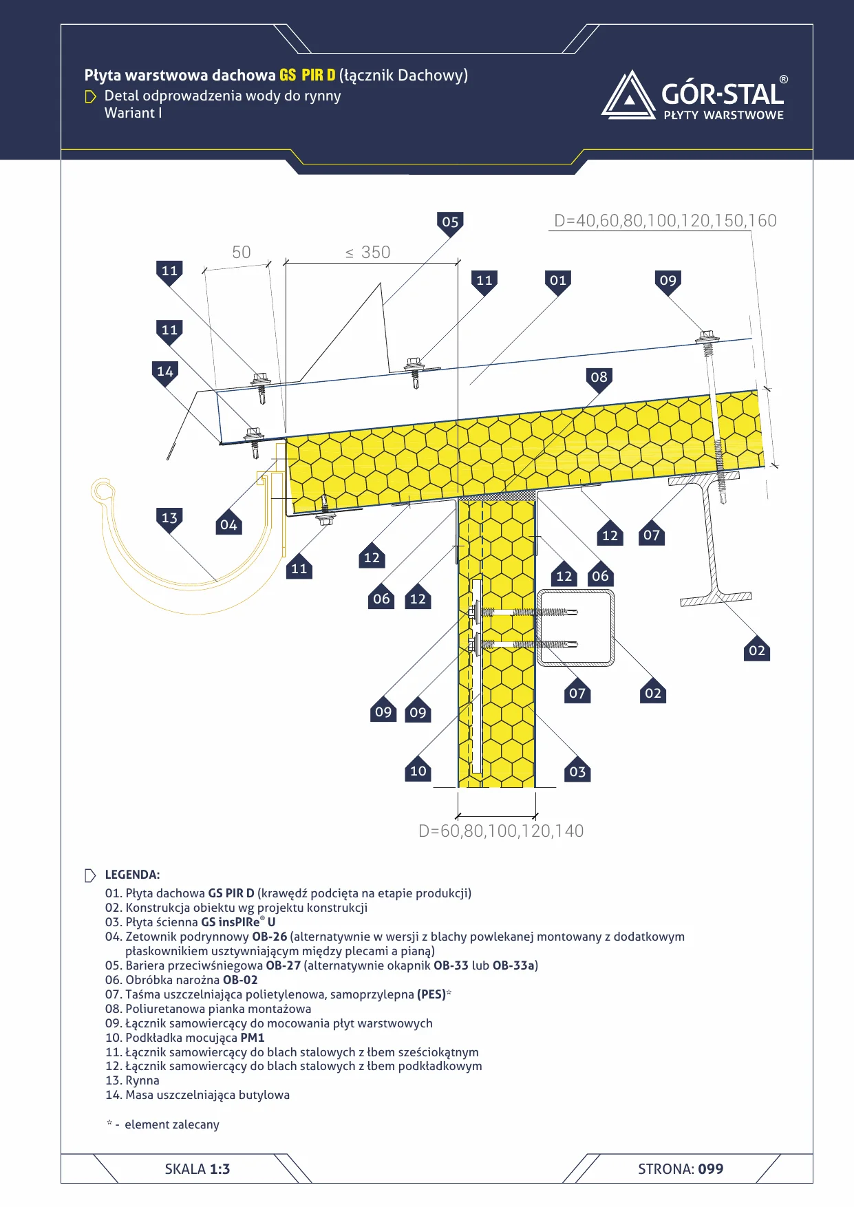
Eaves with gutter — Variant I — insPIRe® D sandwich panel
Eaves detail along the roof slope with water drainage to gutter. Variant I with OB-26 sub-gutter Z-flashing — compact solution with factory-trimmed panel edge.
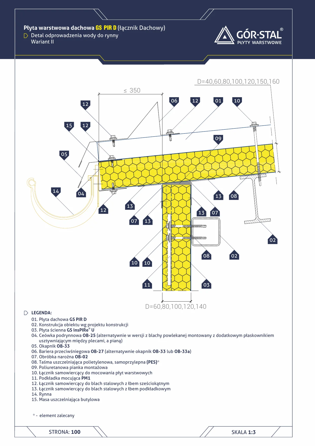
Eaves with gutter — Variant II — insPIRe® D sandwich panel
Premium variant of eaves with gutter — OB-25 under-gutter channel + separate OB-33 drip edge for cleaner visual line. Choice for retail buildings, showrooms, office buildings with exposed eaves.
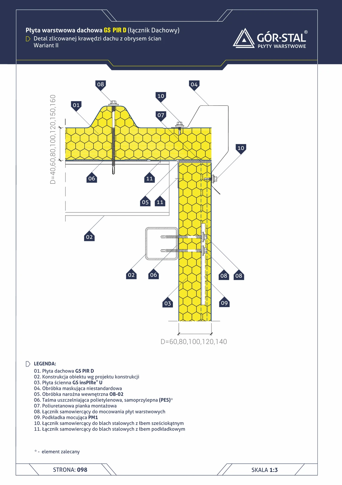
Roof edge flush with wall outline — variant II (GS PIR D)
Variant II of the flush edge with an **additional raised fastener** for reinforcement. Used in halls exposed to stronger wind pressure (zones III/IV).
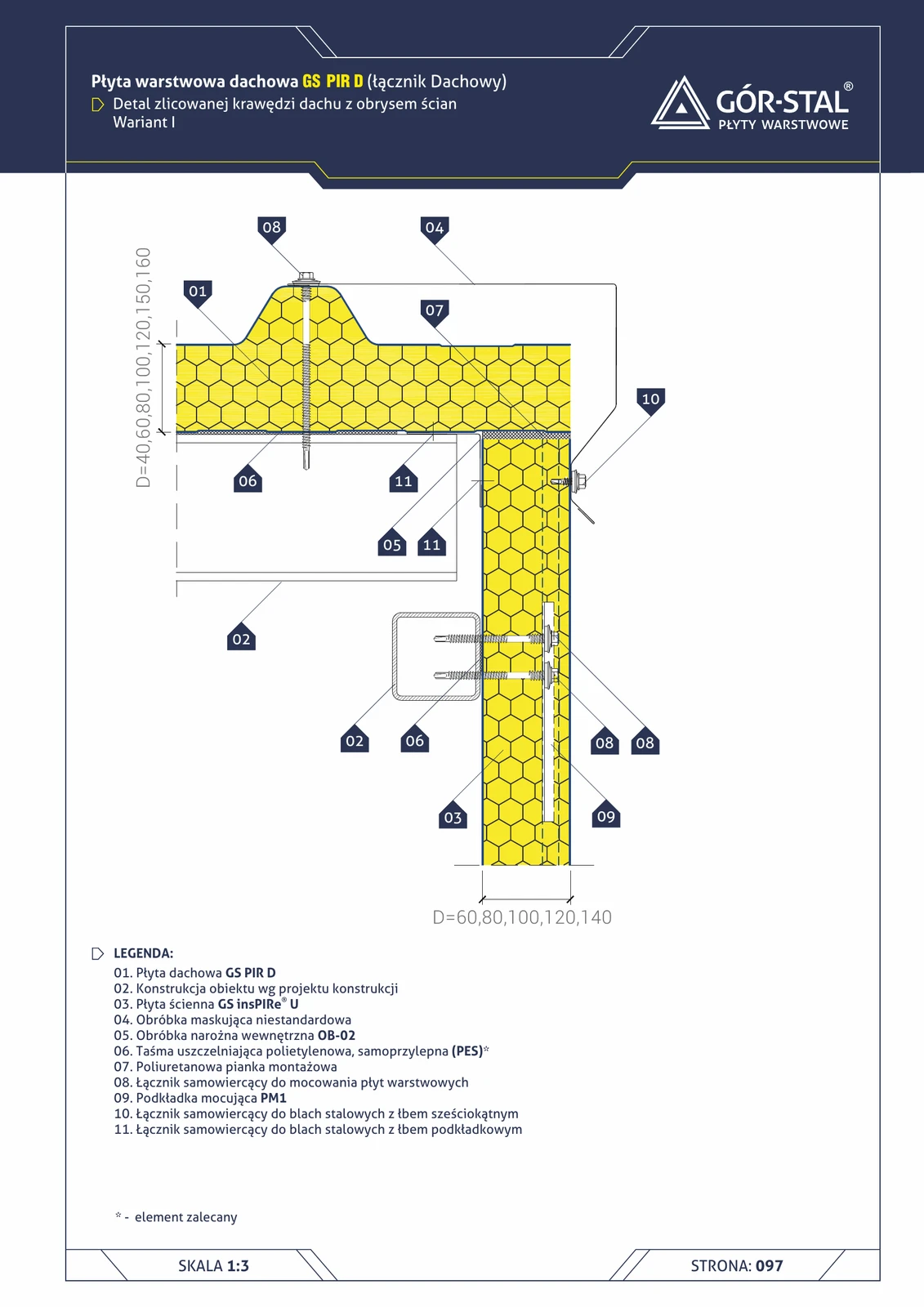
Roof edge flush with wall outline — variant I (GS PIR D)
Roof edge **flush** with the wall line (no projecting eaves) — minimalist geometry. Custom concealment flashing connects the roof panel edge directly with the façade.
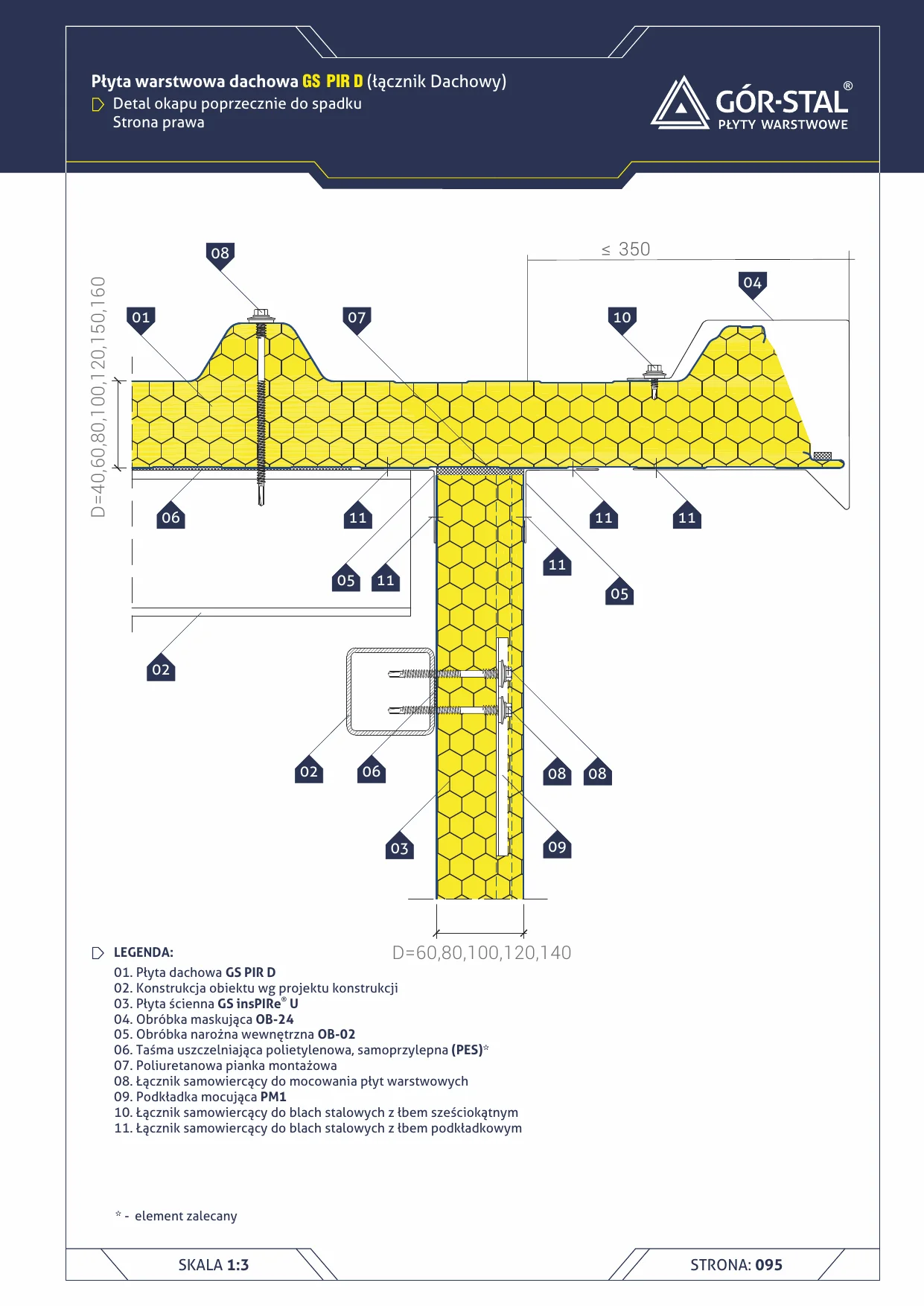
Side eaves — insPIRe® D sandwich panel
Eaves transverse to roof slope — lateral edge where the roof pitch meets the gable wall. Finished with OB-24 trim flashing + OB-02 corner flashing.
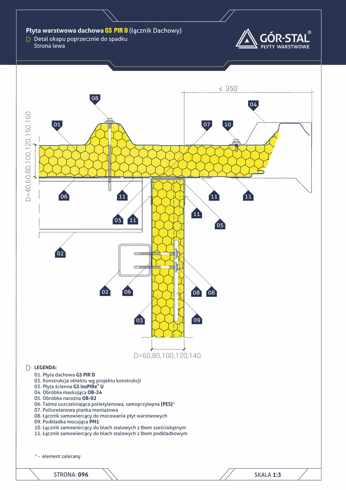
Eaves perpendicular to slope — left side (GS PIR D)
Lateral roof edge (left side, perpendicular to slope) with OB-24 trim. Complements the [okap-poprzeczny-sandwich-d](/wezly-konstrukcyjne/okap-poprzeczny-sandwich-d/) junction (right side).
Parapet (3)
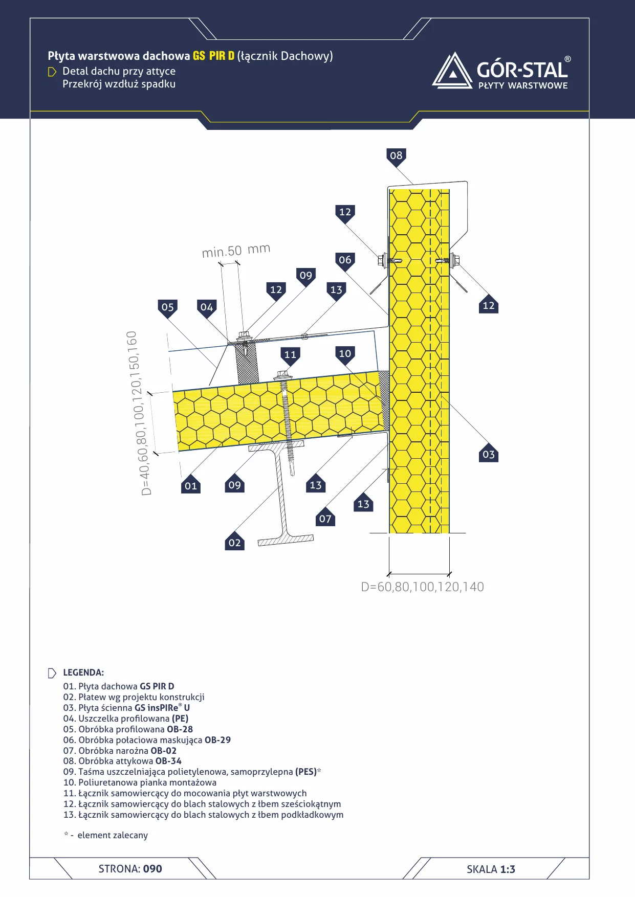
Parapet — section along slope — sandwich panel D
Parapet junction viewed along the roof slope. Roof-to-wall panel connection via OB-29 + OB-02, parapet capped with OB-34 flashing.
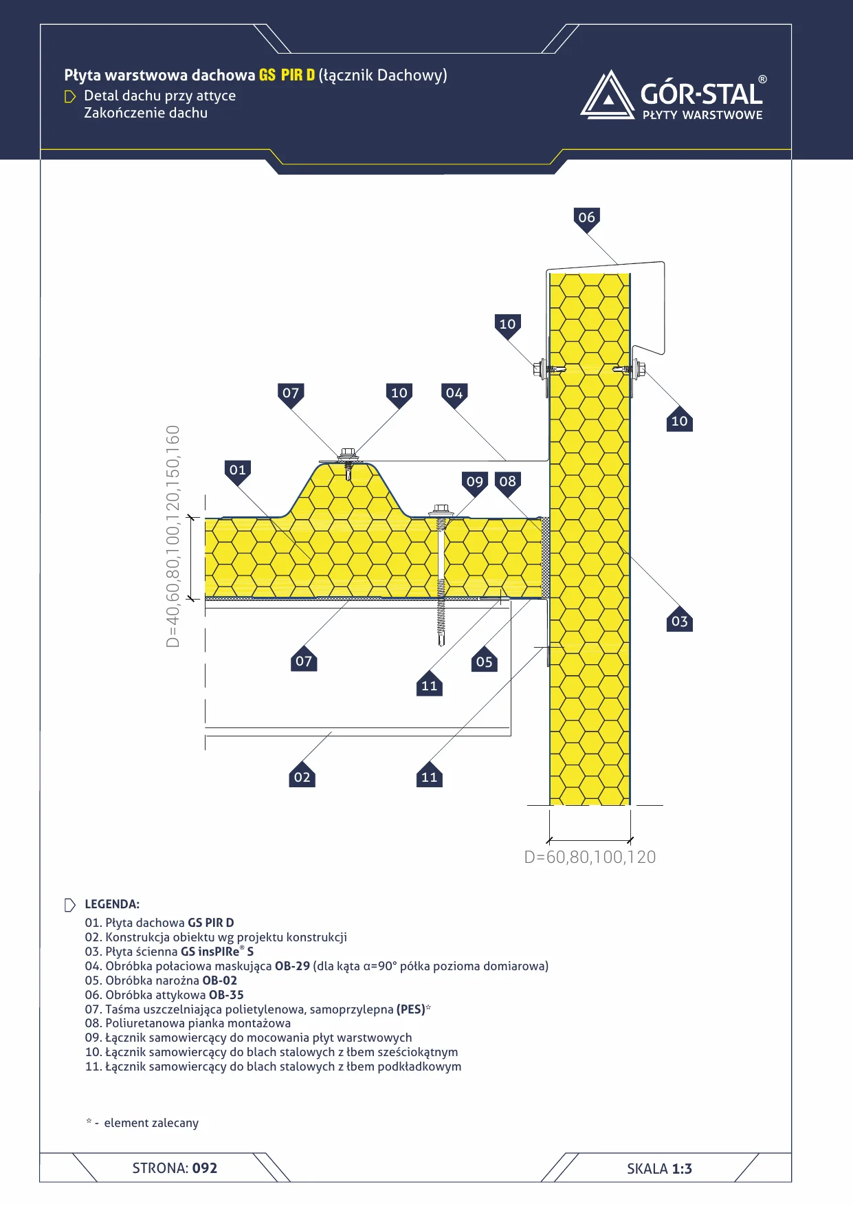
Parapet — roof end — sandwich panel D
Roof end detail at parapet — ridge zone at the wall and roof corner. OB-35 parapet flashing caps the connection, OB-29 covers the slope, OB-02 closes the corner.
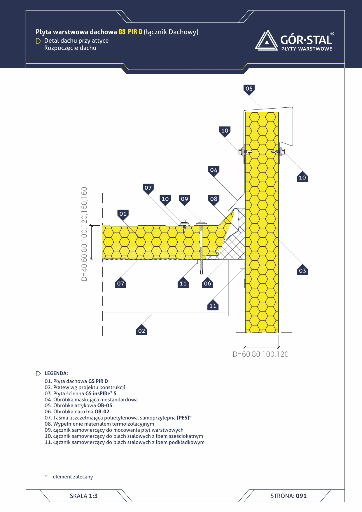
Parapet — roof start — sandwich panel D
Roof start detail at the parapet — eaves zone at the corner of wall and roof. Custom flashing with thermal insulation infill ensuring 3D continuity of insulation.
Base (36)
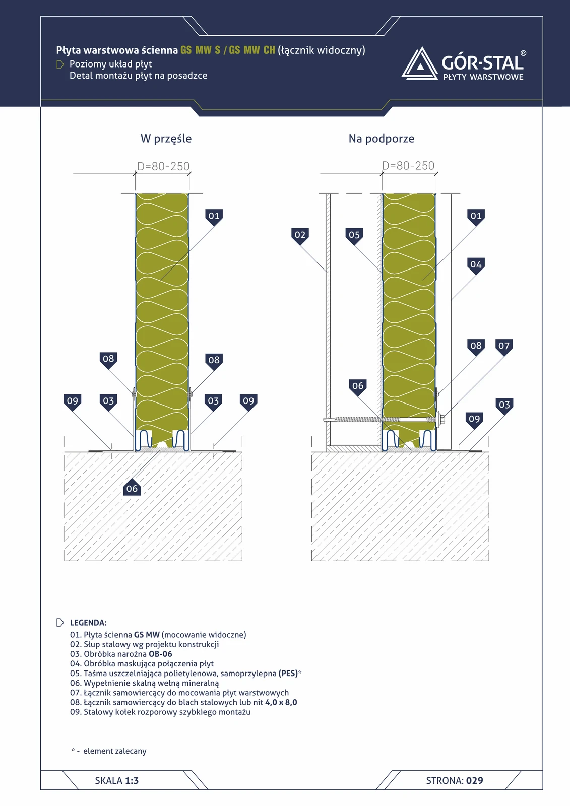
Floor-level installation — horizontal layout of GS MW S/CH panels
Bottom fixing of horizontally-laid GS MW sandwich panels at the concrete floor slab. No sill beam (economy variant). OB-06 corner flashing finishes the bottom edge, mineral wool fills the space at the load-bearing column.
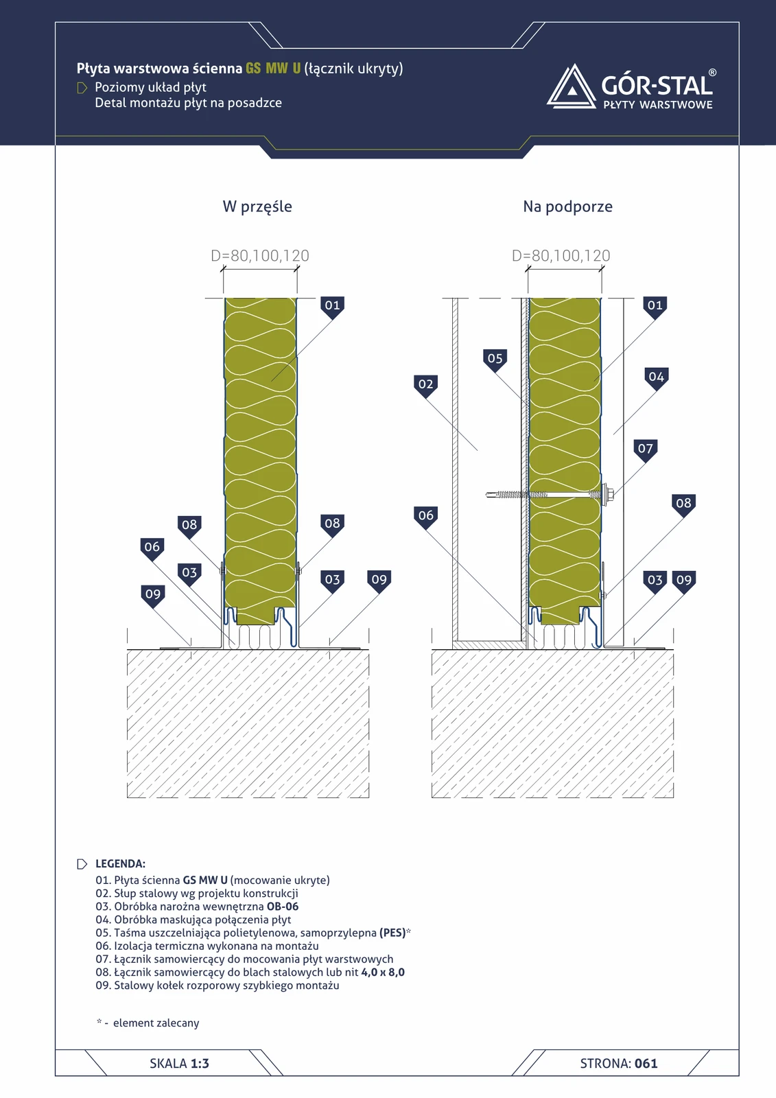
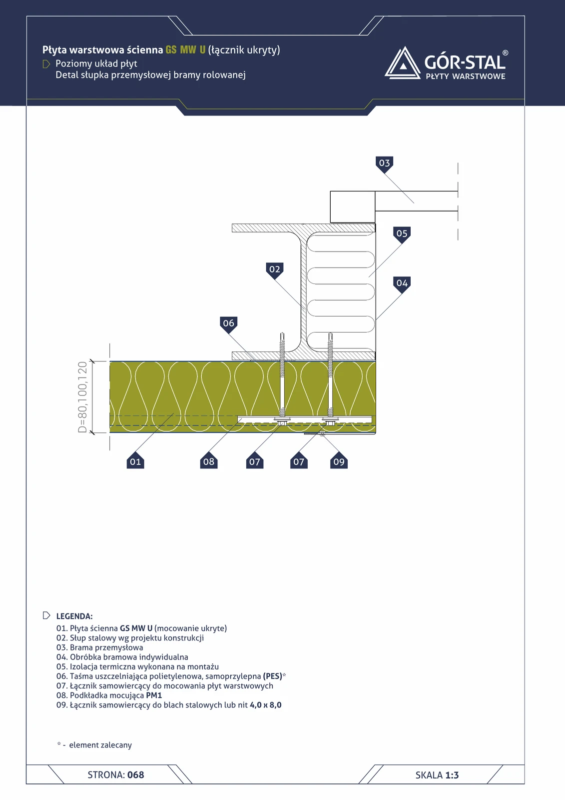
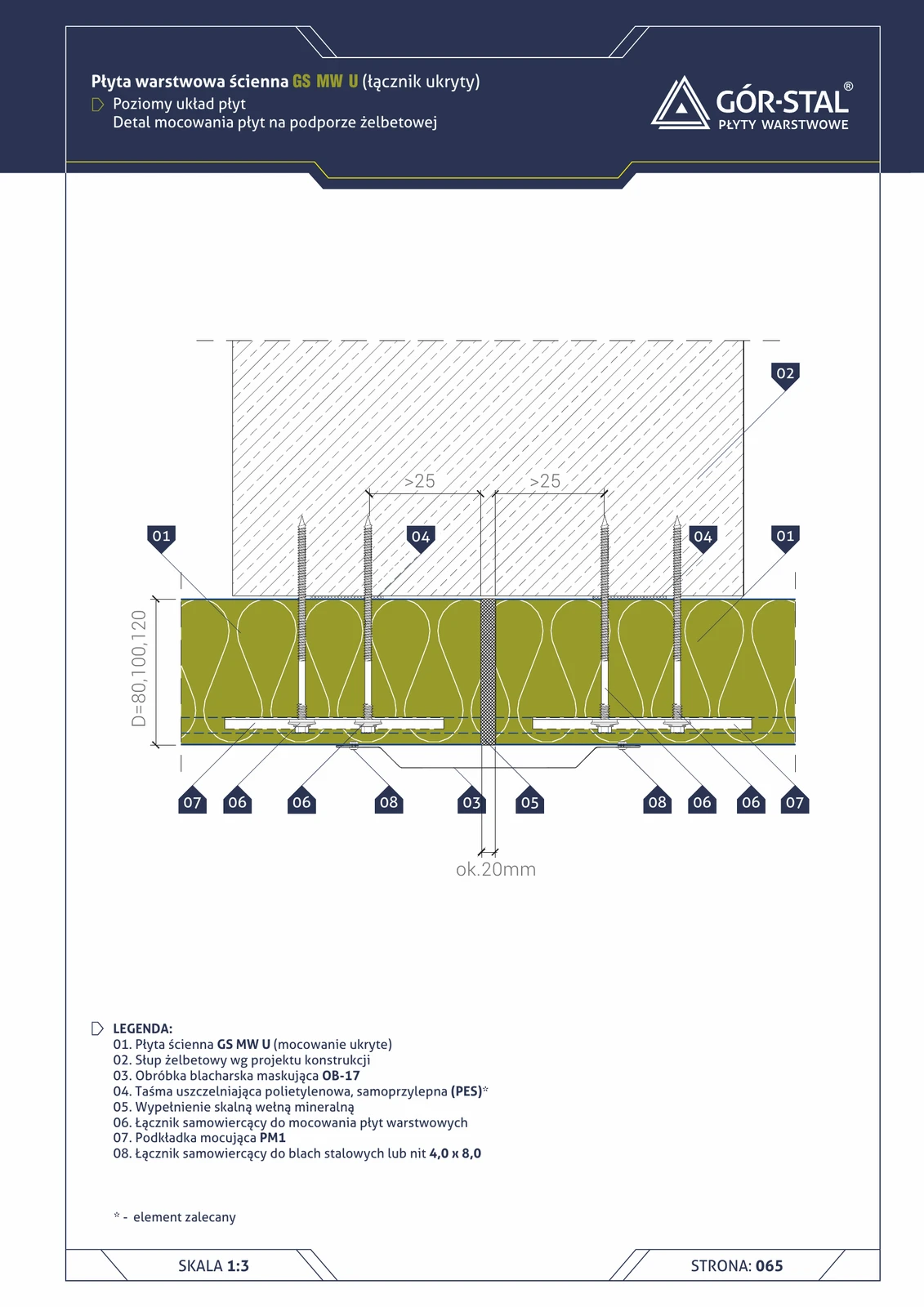
Floor installation — horizontal GS MW U panel layout
Bottom edge of horizontally laid GS MW U premium panels on concrete floor (no sill beam). OB-06 flashing finishes the bottom edge, thermal insulation installed on site.
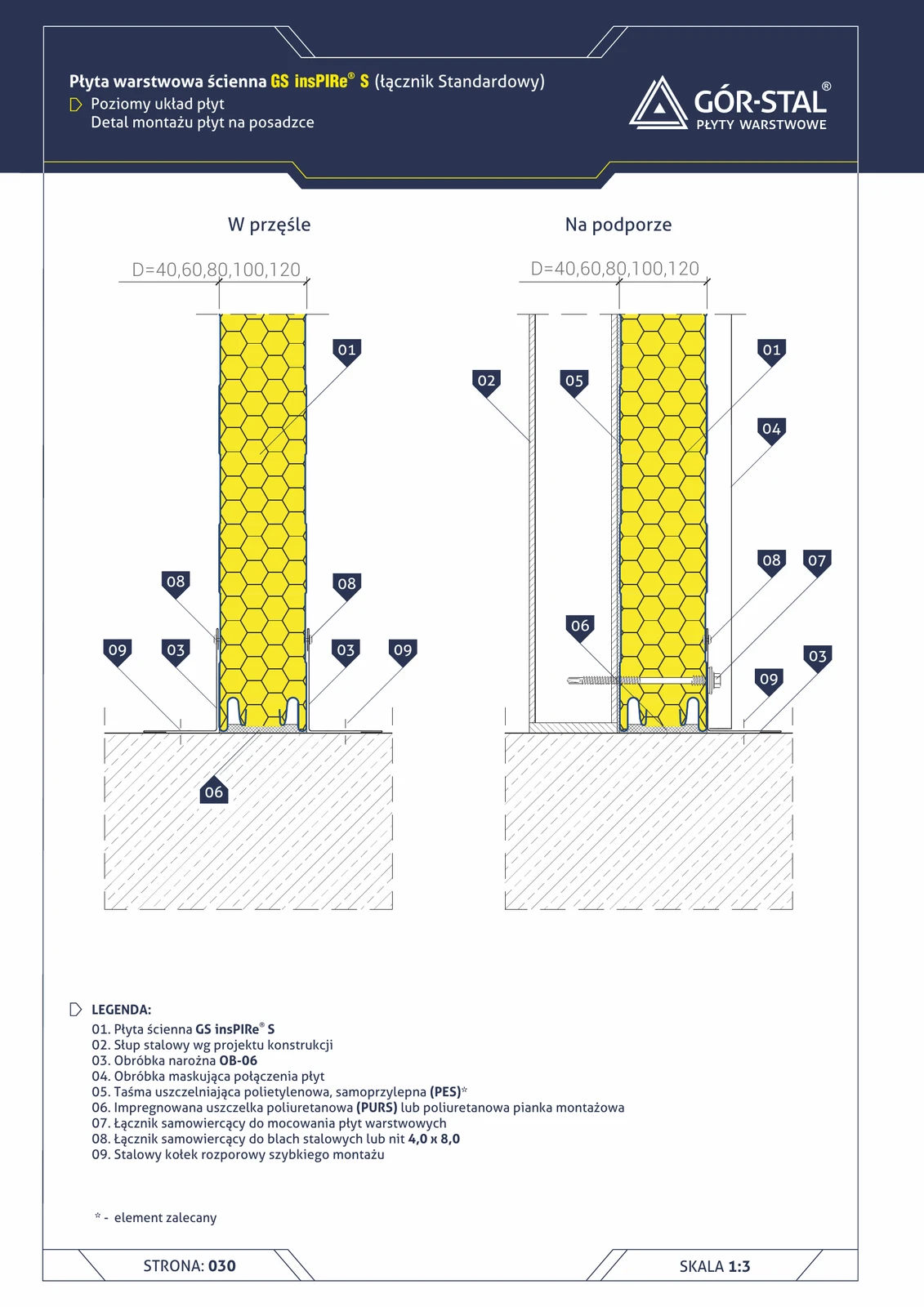
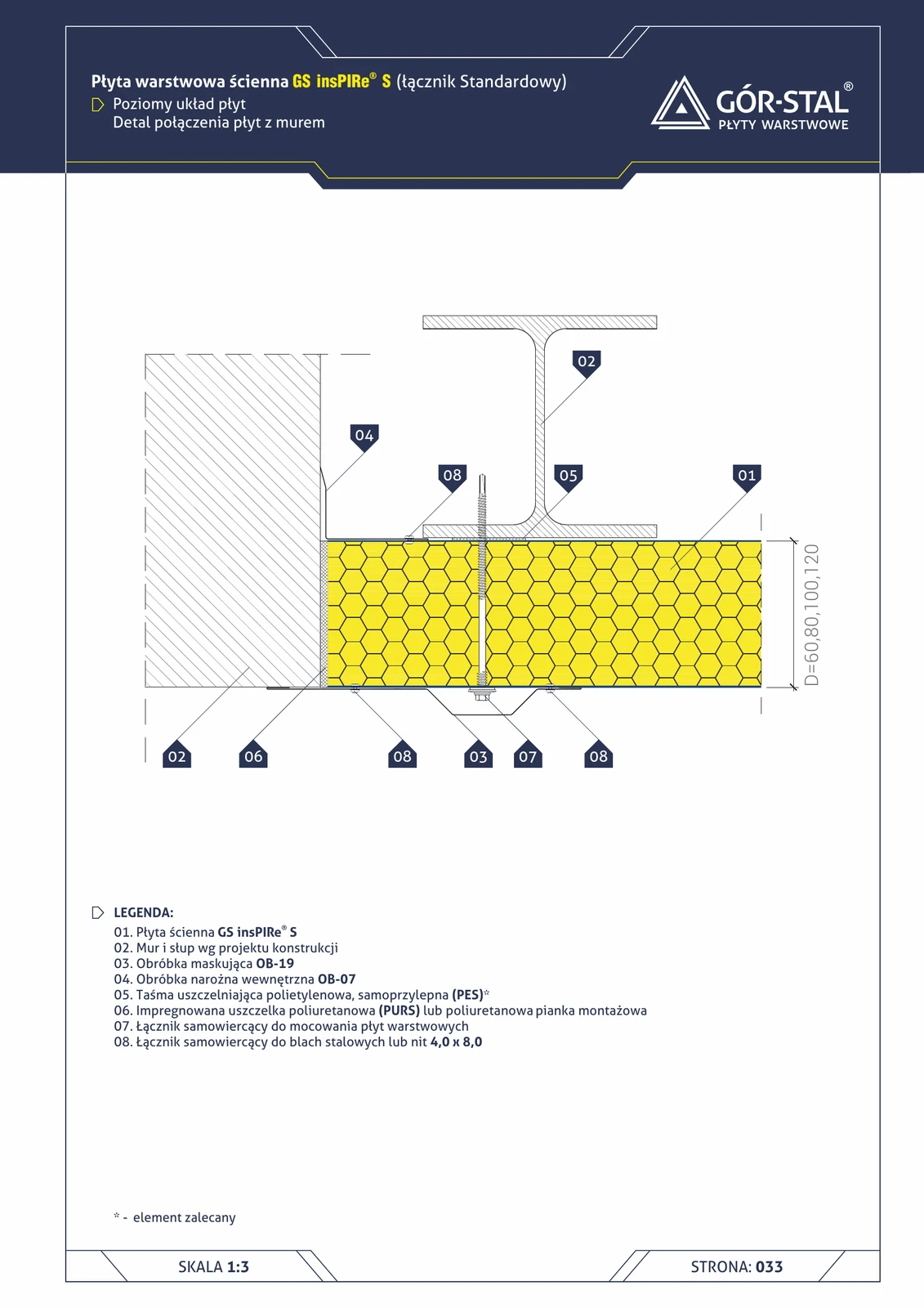
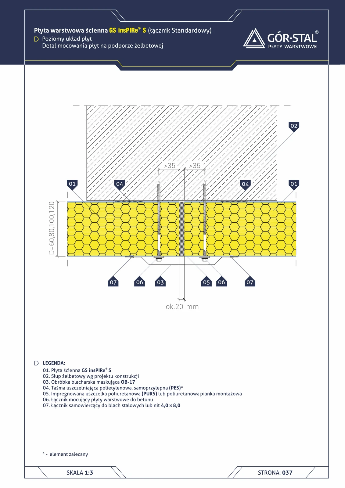
Floor connection — horizontal insPIRe® S panel layout
Bottom edge of horizontally laid PIR panels on concrete floor (without base beam). OB-06 corner flashing finishes the edge, quick-fix expansion anchors secure the structure.
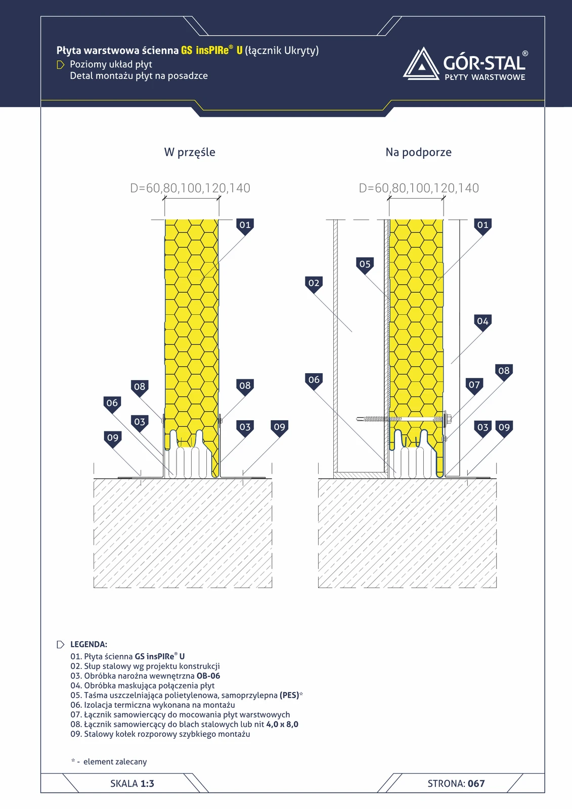
Floor base installation — horizontal layout of insPIRe® U panels
Premium horizontal PIR panels fixed to concrete floor without sill beam. OB-06 finishes the bottom edge, quick-mount expansion anchors.
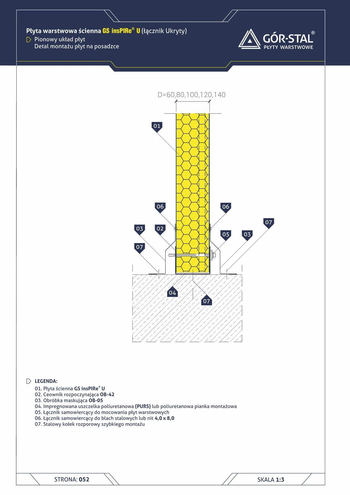
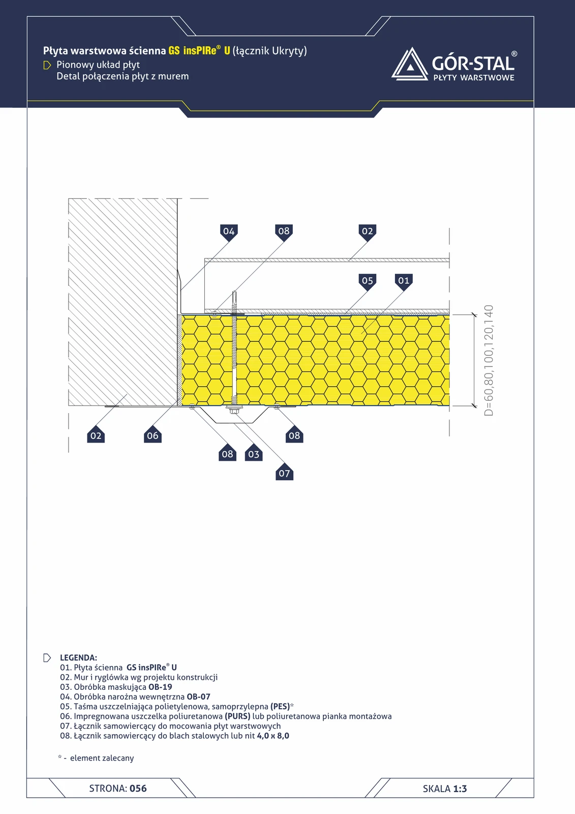
Floor installation — vertical insPIRe® U panel layout
Bottom fixing of vertical premium PIR panels directly to the floor. OB-42 C-profile + OB-05 flashing + expansion anchors.
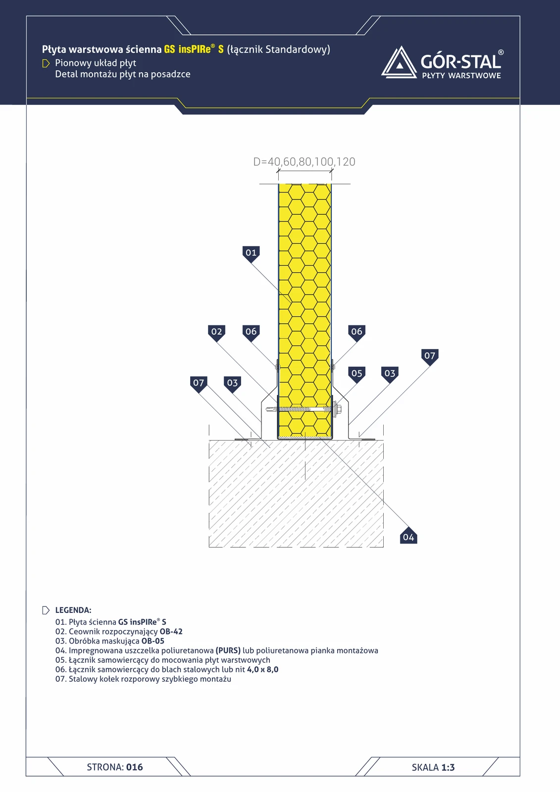
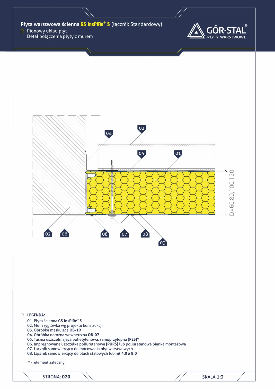
Floor base mounting — vertical insPIRe® S panel layout
Bottom fixing of vertical PIR panels directly to the concrete floor slab. OB-42 starter channel guides the bottom row, OB-05 trim finishes the interior side. Quick-install expansion anchors.
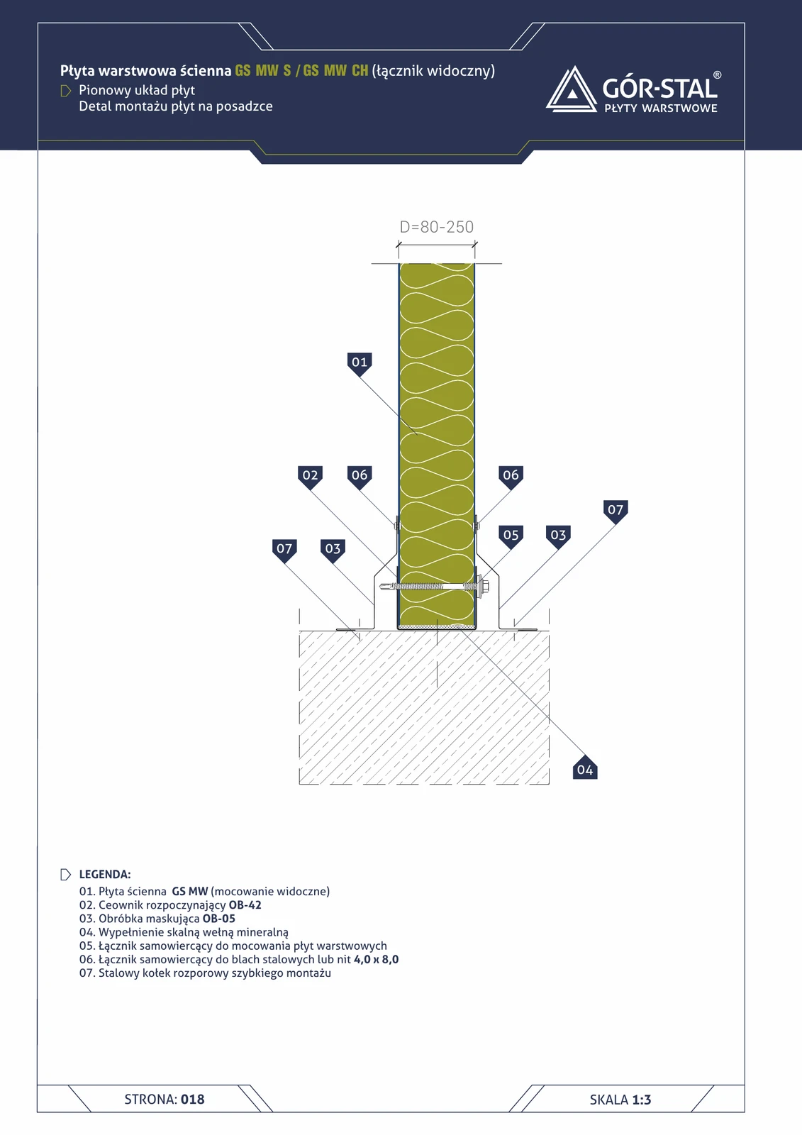
Floor installation — vertical layout of GS MW S/CH panels
Bottom fixing of vertically installed GS MW S/CH sandwich panels directly to the concrete floor. Starting OB-42 channel guides and seals the lower panel edge, anchored to the substrate with steel quick-installation expansion anchors.
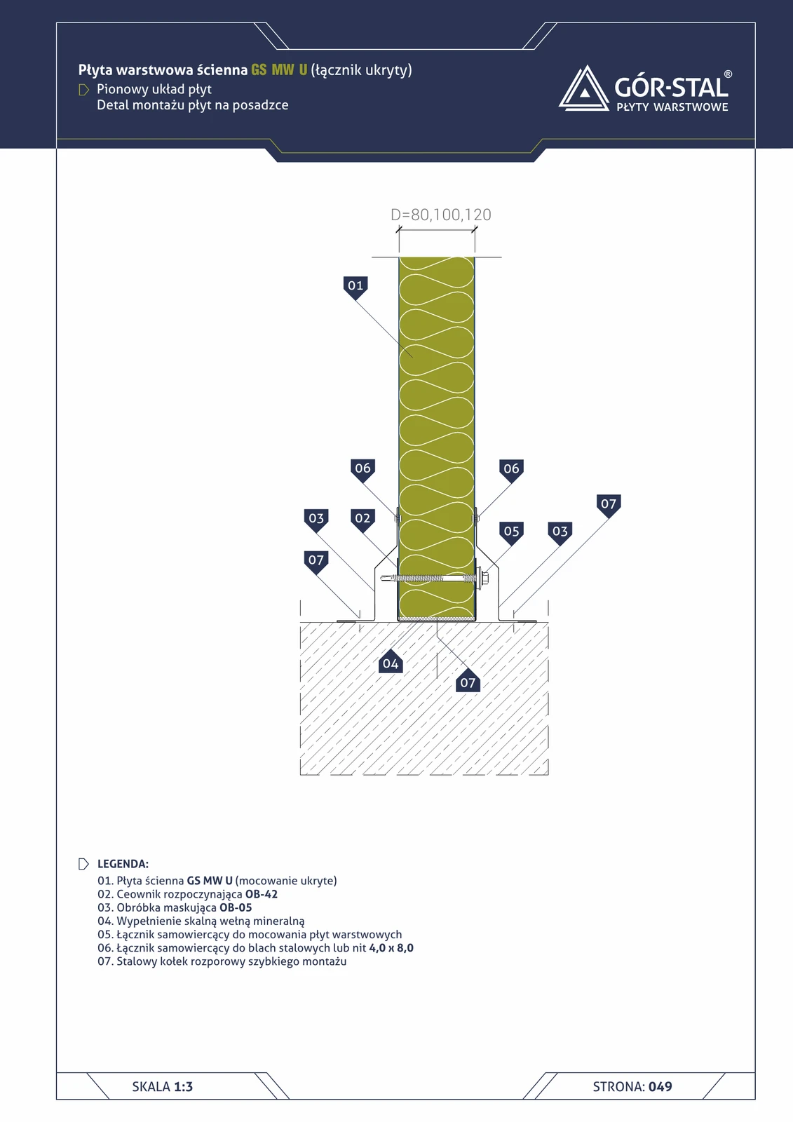
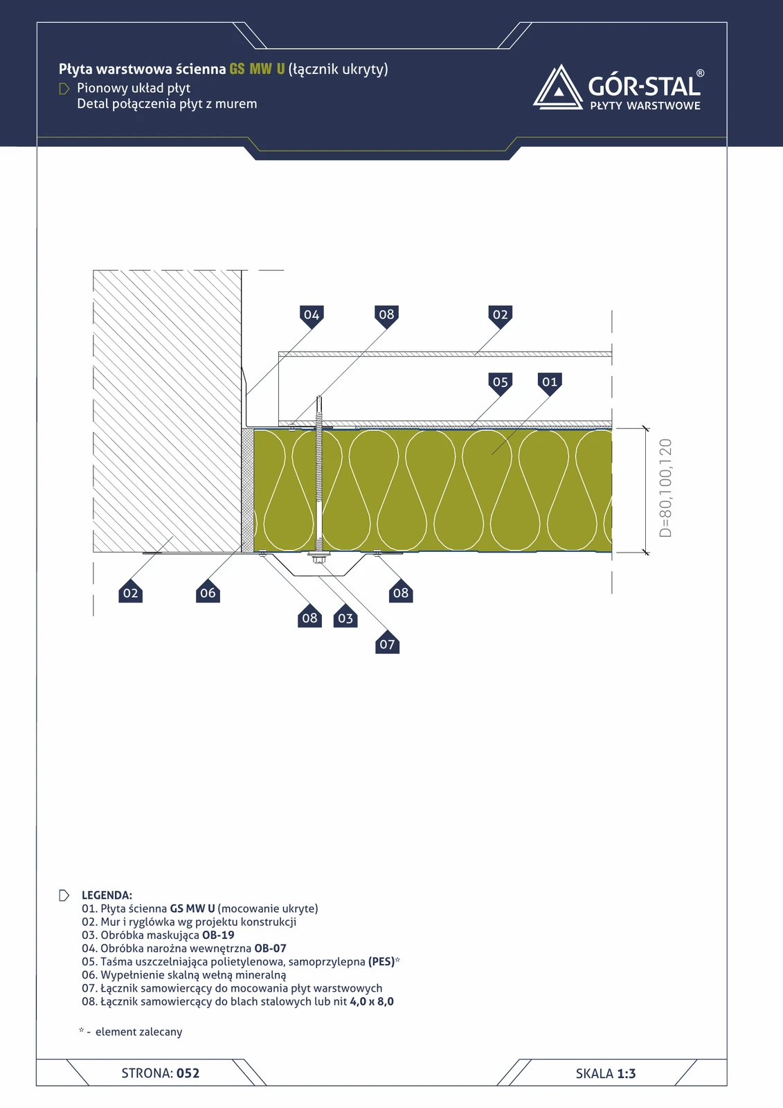
Floor mounting — vertical GS MW U panel layout
Bottom fixing of vertical GS MW U panels directly to concrete floor (without base beam). Identical construction as in S/CH (page 20): OB-42 channel, OB-05 flashing, mineral wool in the installation cavity.
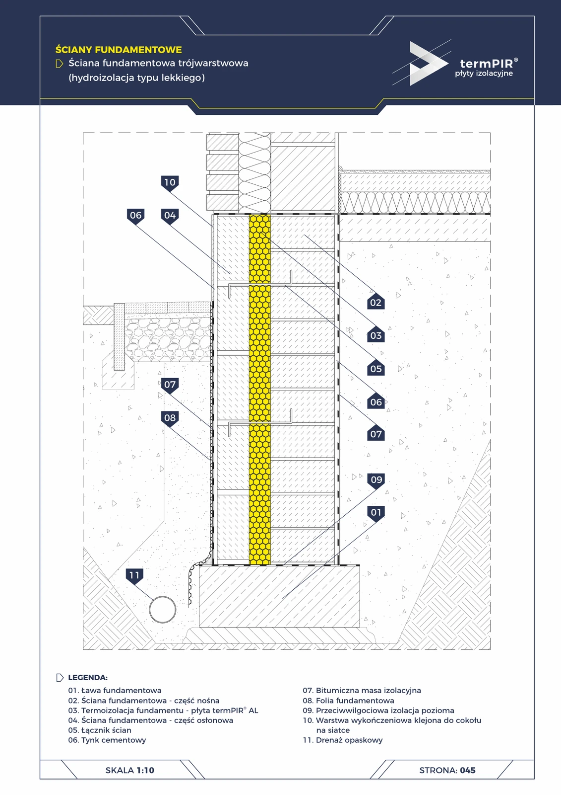
Three-layer foundation wall (termPIR® AL in cavity)
3-layer foundation wall variant: termPIR® AL placed in the cavity between the load-bearing and cladding part of the foundation. Used for buildings with clinker façades — continuation of the 3-layer structure from floor slab to roof.
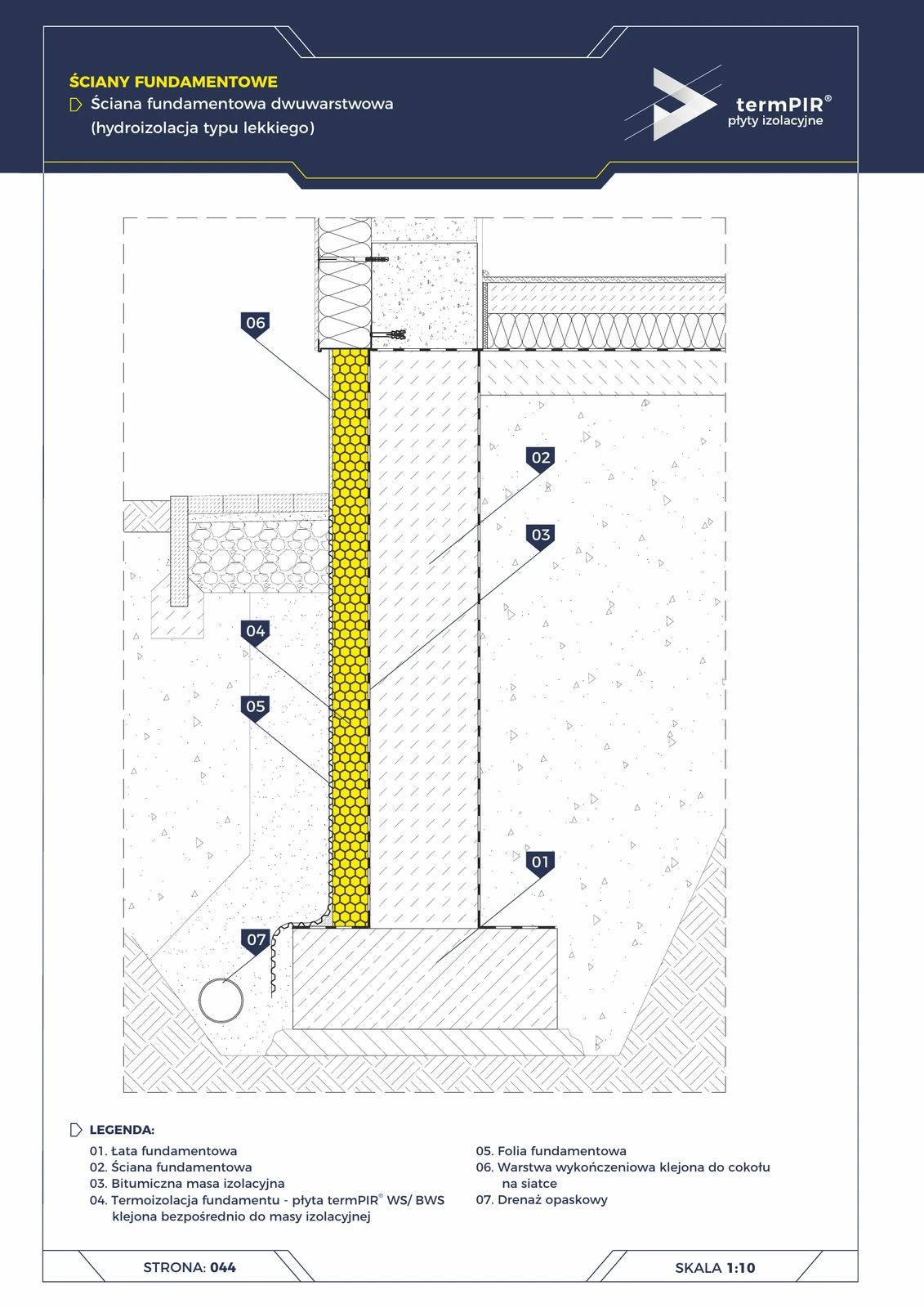
Two-layer foundation wall (termPIR® WS + bitumen)
Classic foundation wall insulation. termPIR® WS panels (waterproof, class W2L) bonded directly to bituminous coating. Dimpled foundation membrane + perimeter drainage protect against water pressure. The most cost-effective and reliable solution.
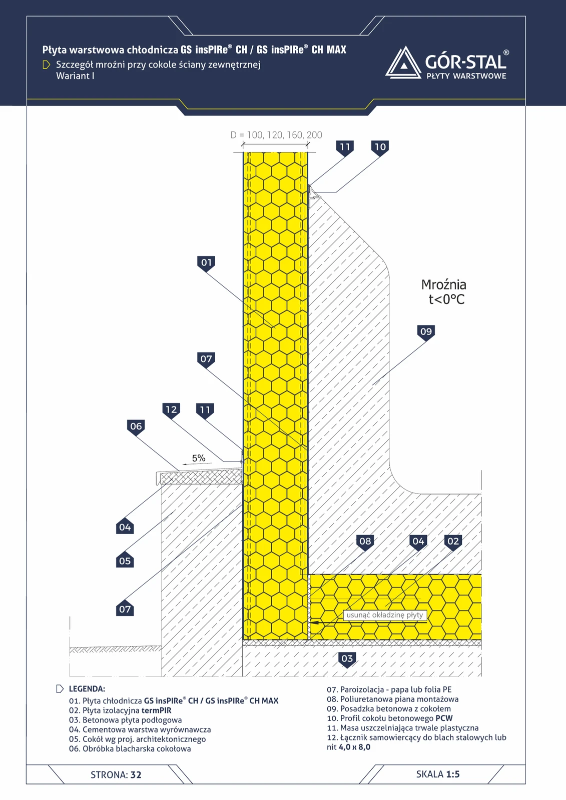
Freezer — external wall base, Variant I
Full sub-floor insulation system for freezer rooms — **termPIR under the concrete floor slab** + vapour barrier + PVC base profile. Variant I = full layout with all layers. Required for freezer rooms with a 50°C gradient and above.
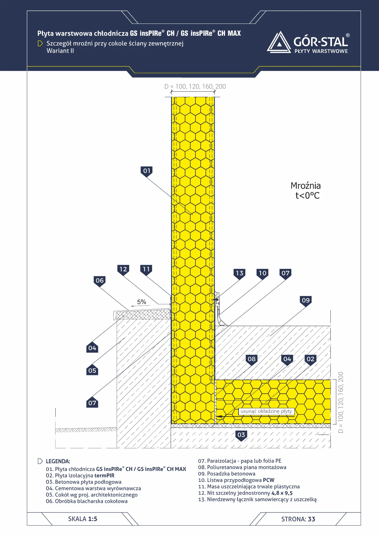
Freezer base at external wall — Variant II
Alternative freezer base detail (<0°C) — PVC skirting instead of concrete plinth. Under-floor termPIR® insulation + PE vapour barrier. Easier renovation than Variant I.
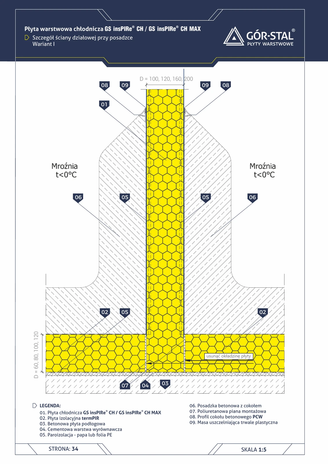
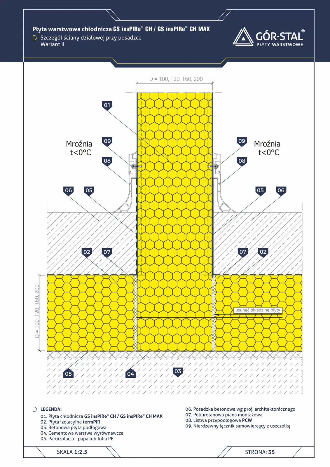
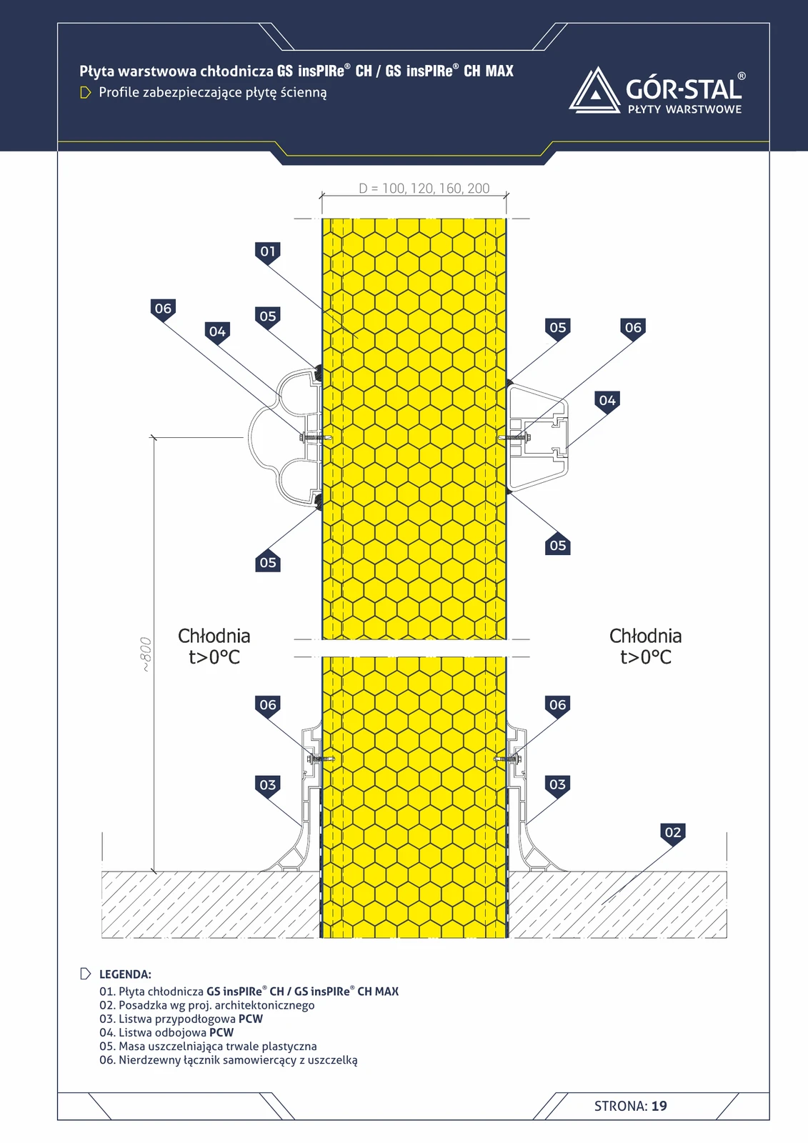
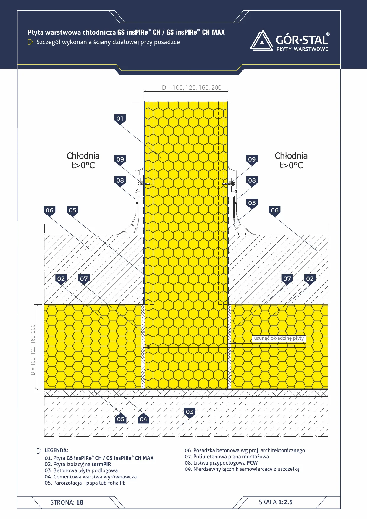
Freezer partition wall at floor — Variant I
Detail of the lower fixing of a freezer partition wall with a **PVC concrete plinth profile**. Complete sub-floor build-up: termPIR + vapour barrier + concrete floor with plinth.
Freezer partition wall at floor — Variant II
Variant II with **PVC skirting** instead of the concrete plinth profile (variant I, p. 36). Less massive finish, better when heavy concrete structures are to be avoided.

Plinth — 2-layer basement wall — termPIR® WS
Economical cross-section through a basement wall with termPIR® WS insulation (glass veil on both sides) bonded directly to bituminous waterproofing compound. Standard for single-family homes with a usable basement.
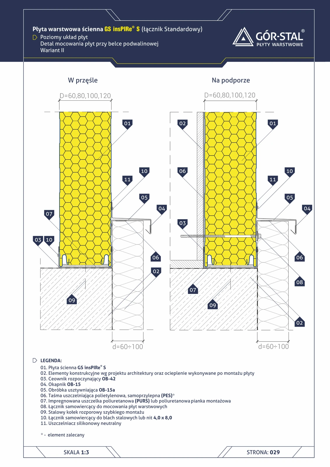
Plinth at sill beam — horizontal insPIRe® S panel layout, variant II
Variant II with OB-42 channel + two-piece OB-15 + OB-15a stiffening drip flashing. Alternative to variant I — preferred when the sill beam is narrower or aesthetics require a lighter drip flashing.
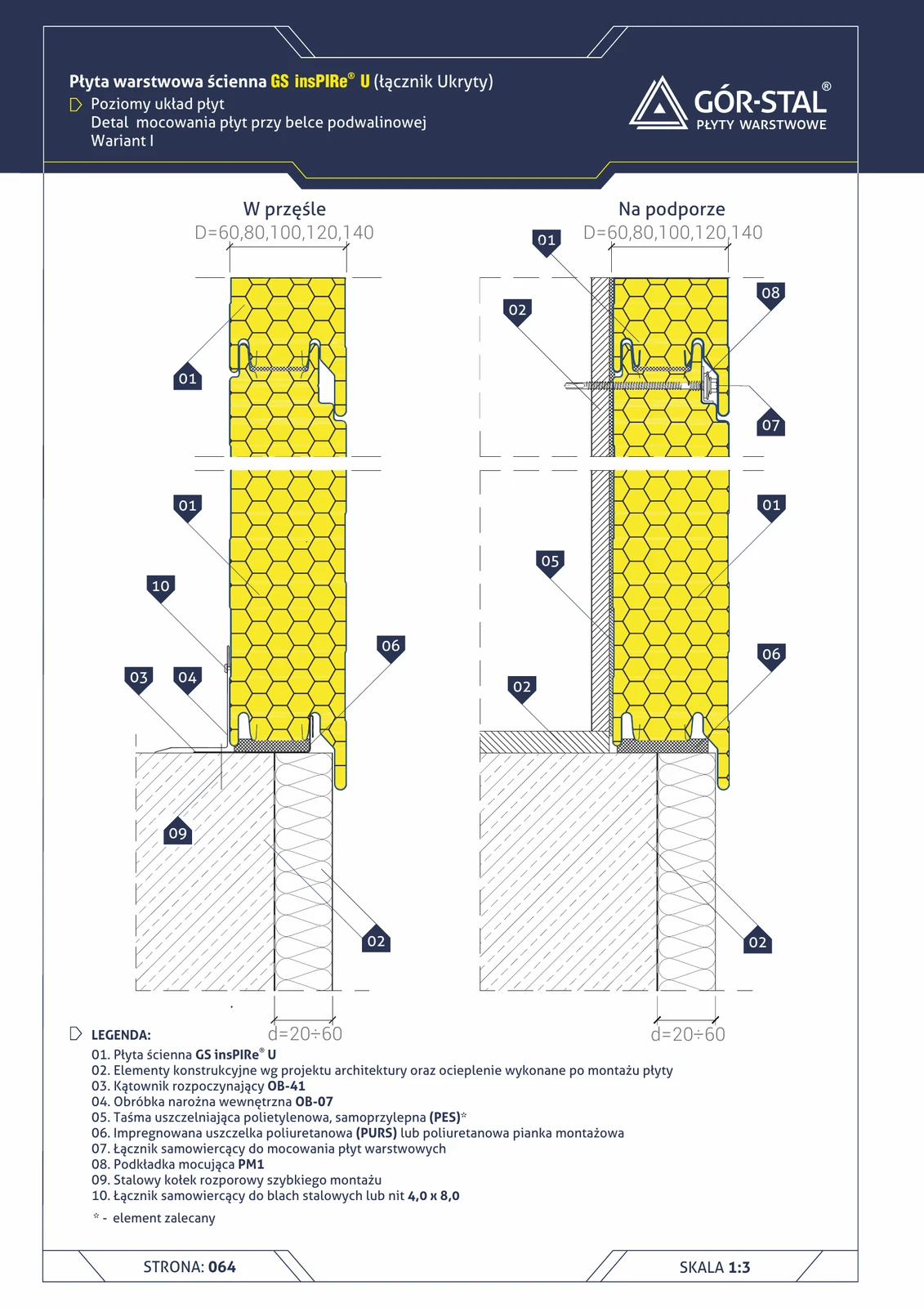
Plinth at sill beam — horizontal insPIRe® U panel layout, variant I
Premium plinth with hidden fastening in horizontal PIR layout. Variant I (d=20-60 mm) with OB-41 angle + OB-07 internal + PM1.
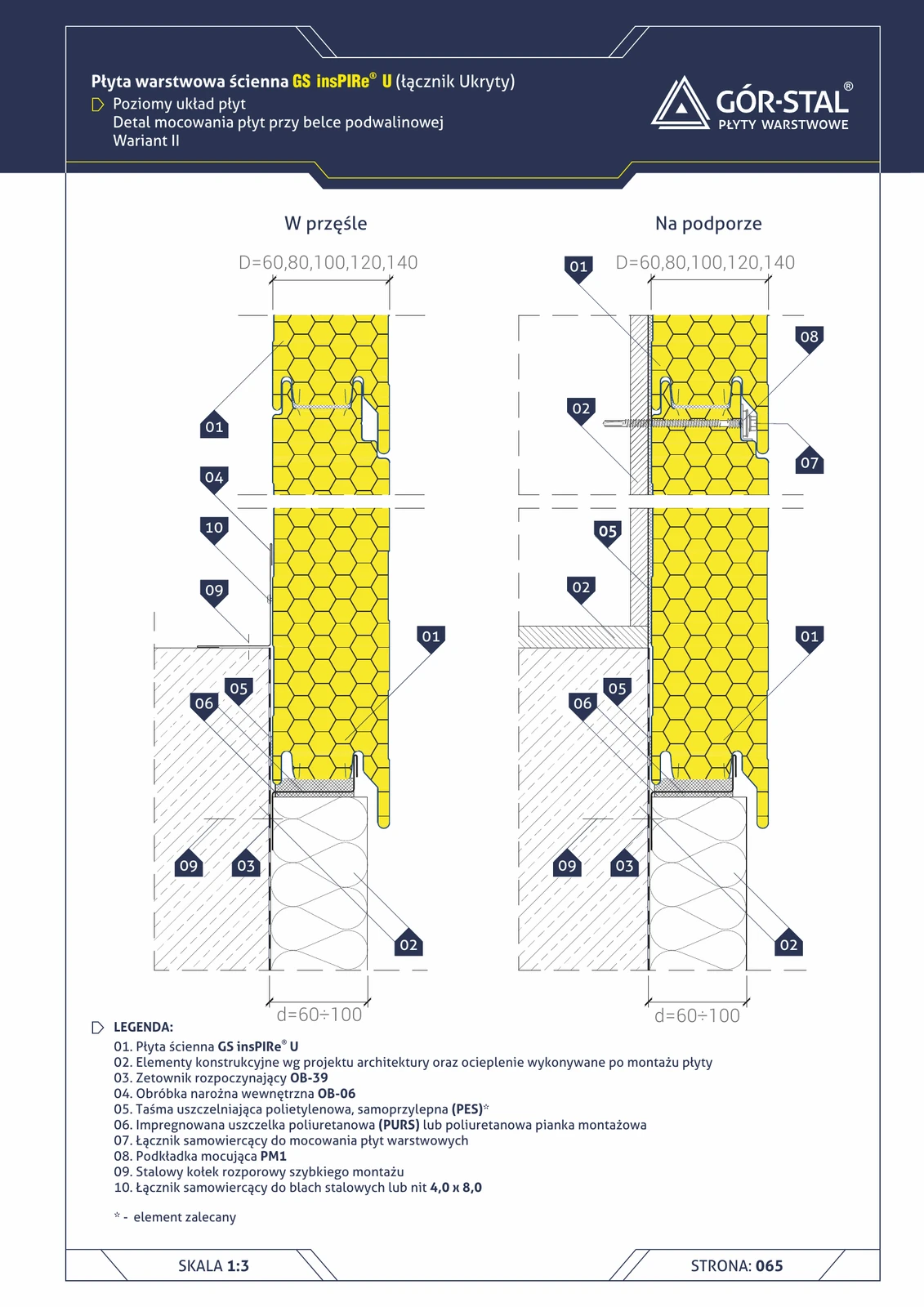
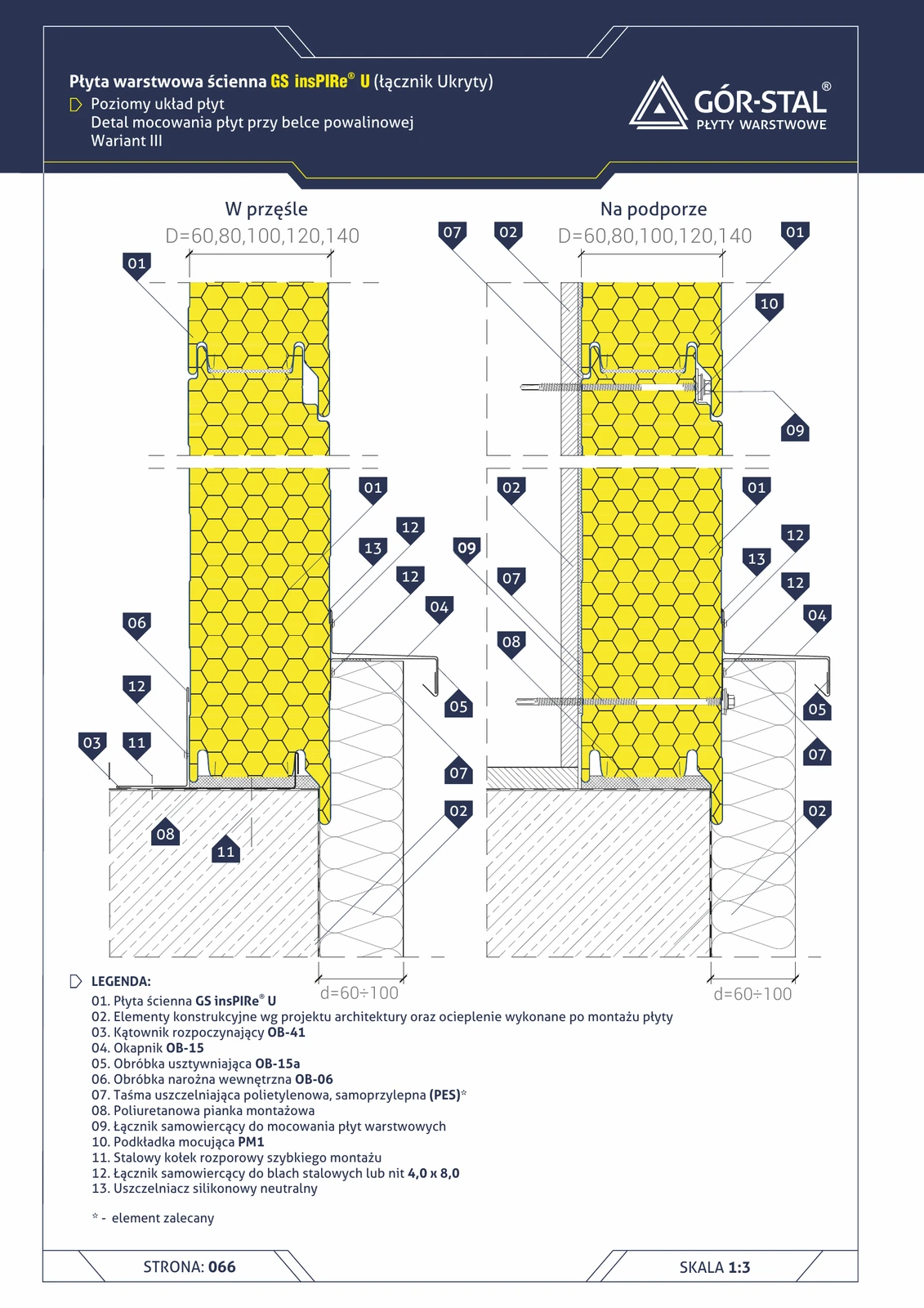
Plinth at sill beam — horizontal insPIRe® U panel layout, variant II
Variant II of the horizontal U plinth with greater projection (d=60-100 mm) and OB-39 Z-profile (instead of OB-41 angle from variant I). A stiffer guide rail for tall premium façades.
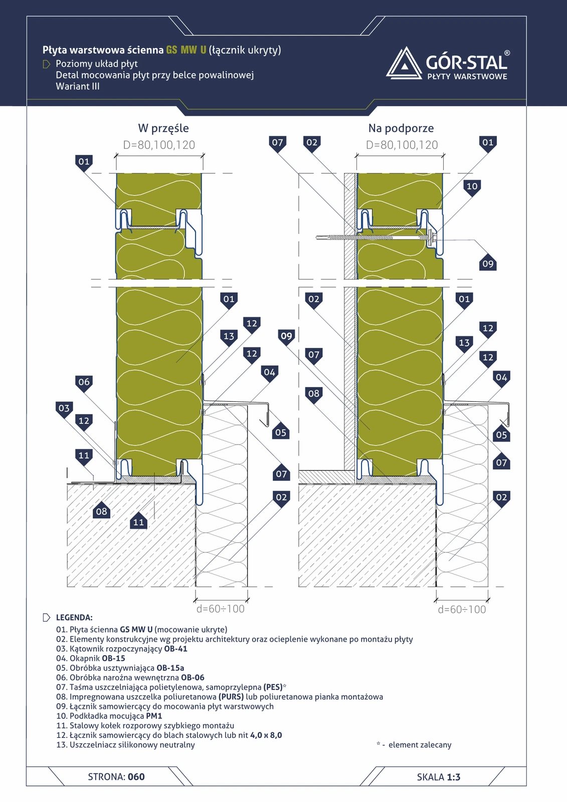
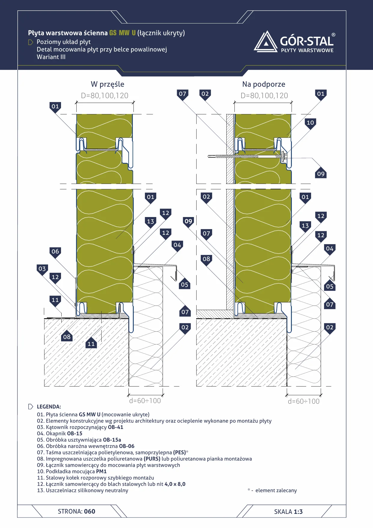
Plinth at sill beam — horizontal insPIRe® U panel layout, variant III
Third variant of horizontal U plinth — analogous to variant II but with two-part OB-15 drip flashing + OB-15a stiffener instead of OB-39 Z-profile. Lighter aesthetics.
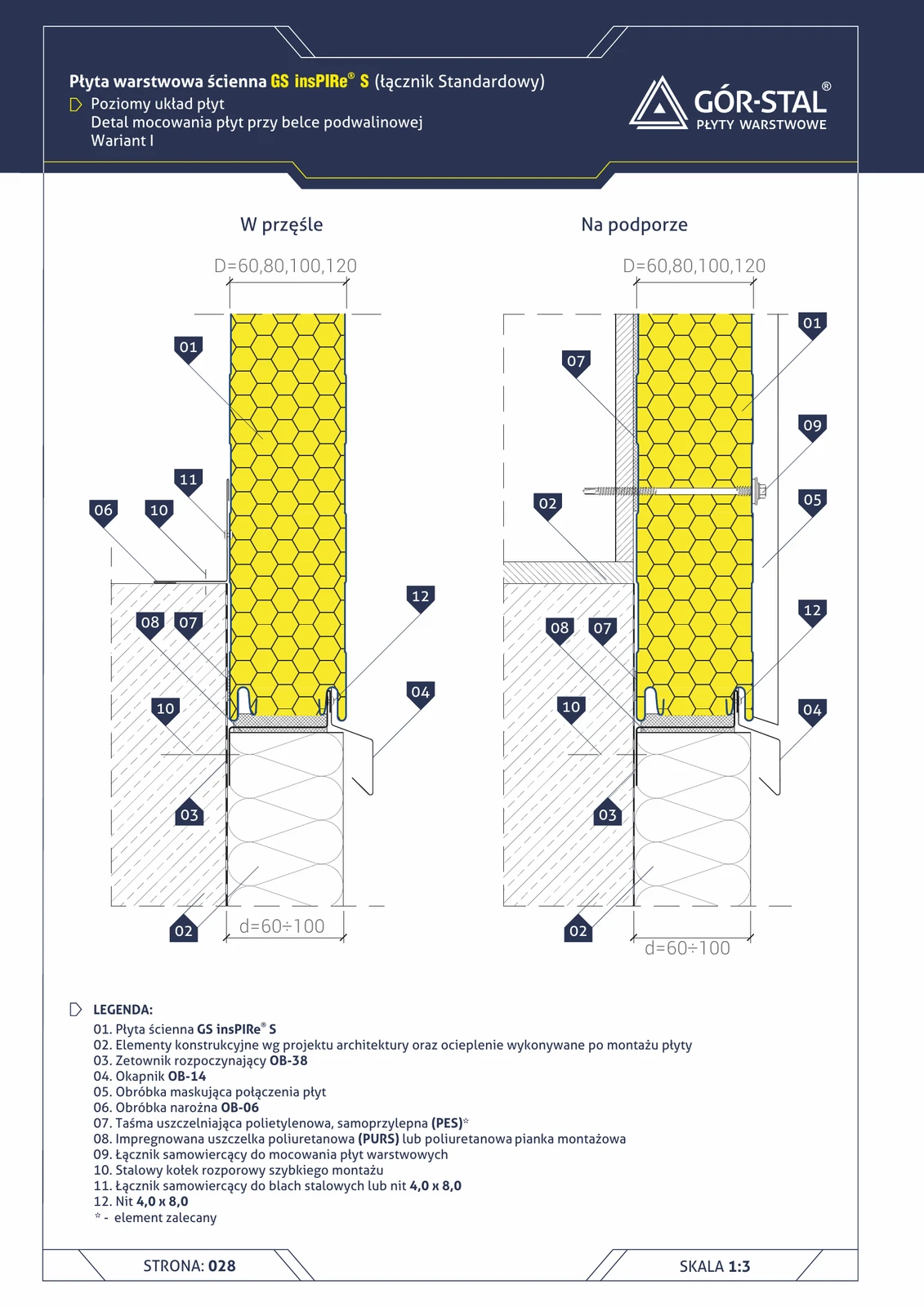
Plinth at sill beam — horizontal arrangement of insPIRe® S panels, variant I
Variant I with OB-38 Z-profile as a guide rail + OB-14 drip flashing + OB-06 internal corner. Identical design to MiWo S/CH horizontal (page 29) with a PIR core instead of mineral wool.
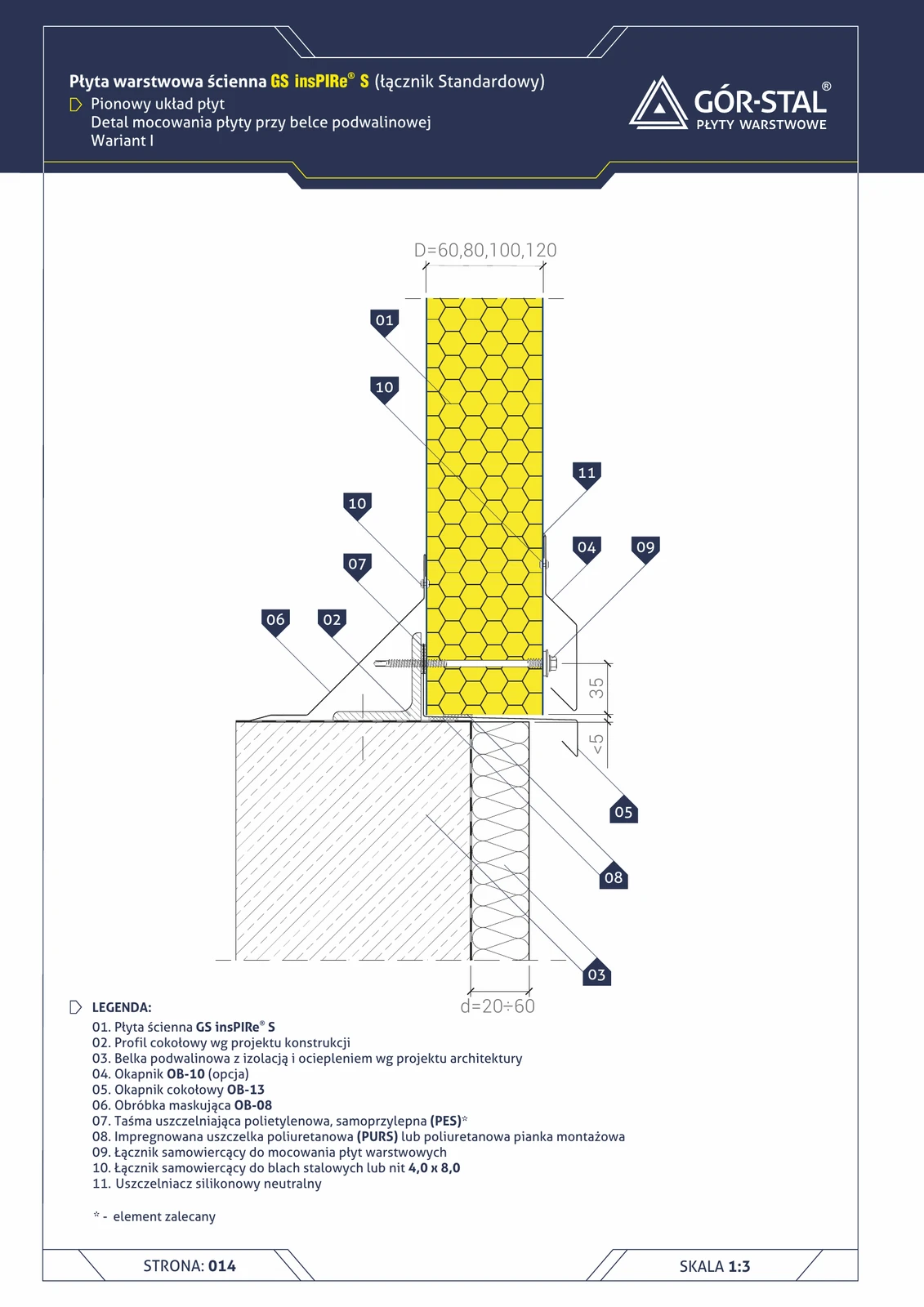
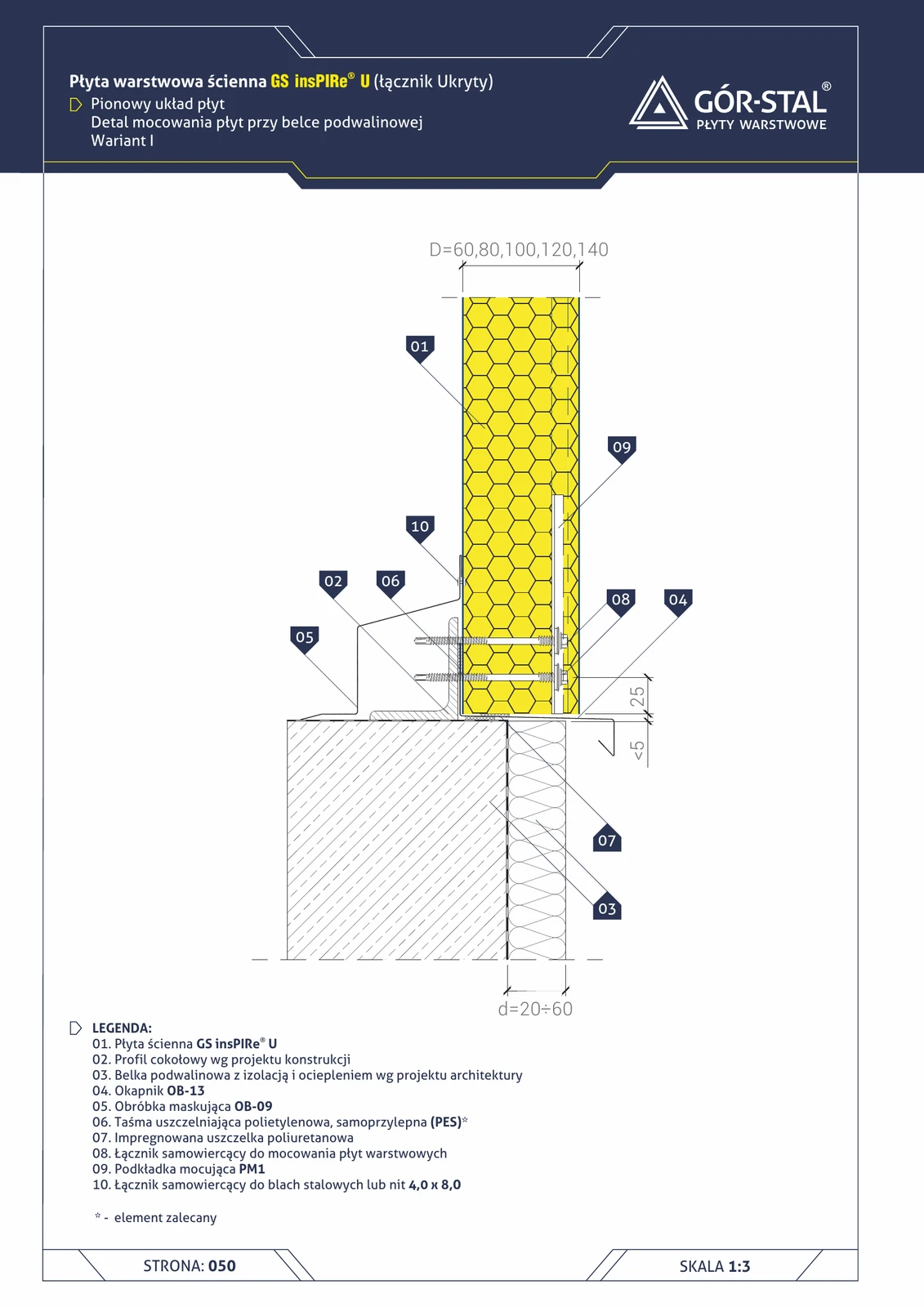
Plinth at sill beam — vertical layout of insPIRe® S panels, variant I
Standard plinth for vertical PIR layout. Variant I (d=20-60 mm) with OB-13 flashing + optional OB-10 + OB-08 internal cover trim. PES seals + PURS foam + silicone.
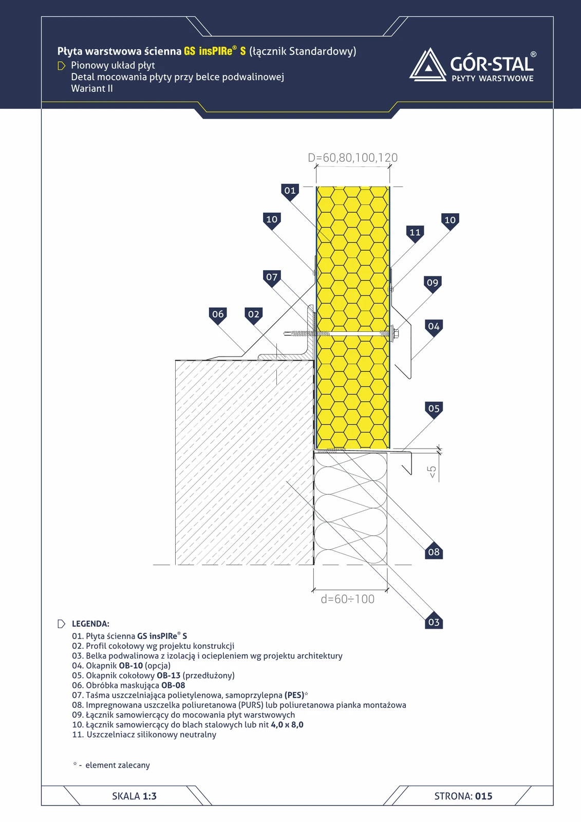
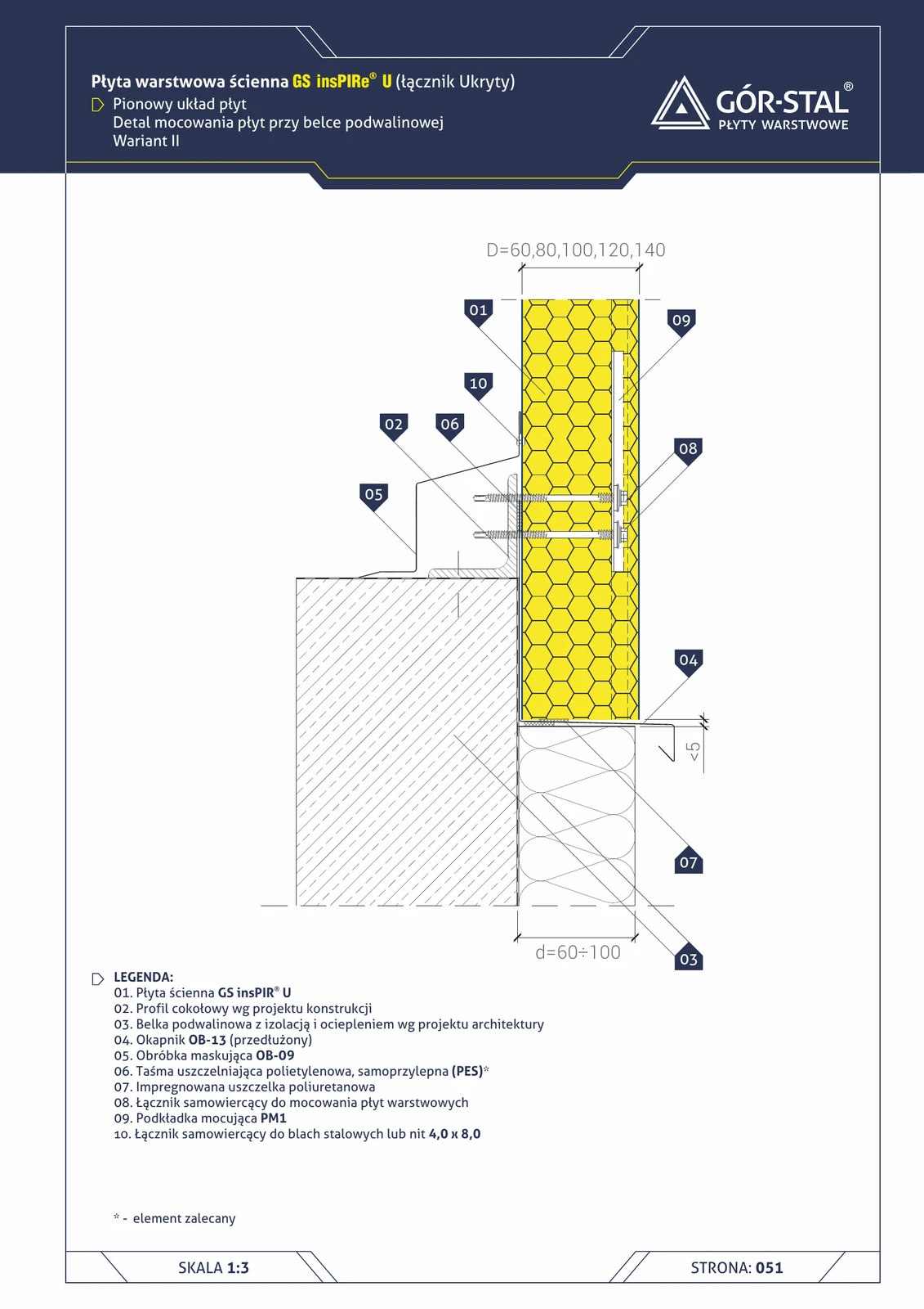
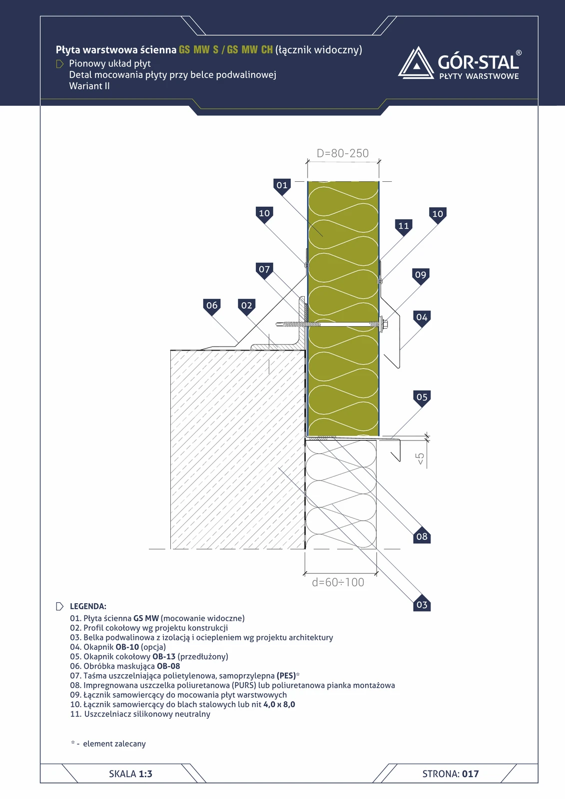
Plinth at sill beam — vertical layout of insPIRe® S panels, variant II
Variant II with greater overhang (d=60-100 mm) — for tall facades, heavy rain, aggressive climate. Same design as variant I, longer OB-13.
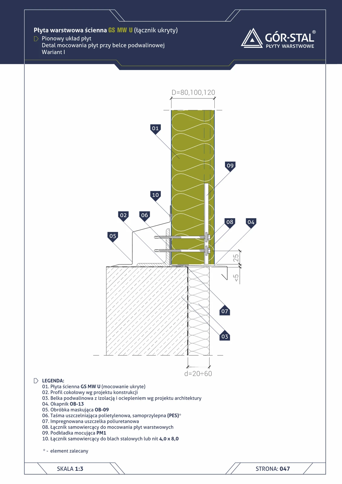
Plinth at sole plate — vertical insPIRe® U panel layout, variant I
Premium plinth with concealed PIR fixing. Variant I (d=20-60 mm) — minimalist drip flashing. PM1 + OB-13 + OB-09 cover trim (different geometry for U-joint).
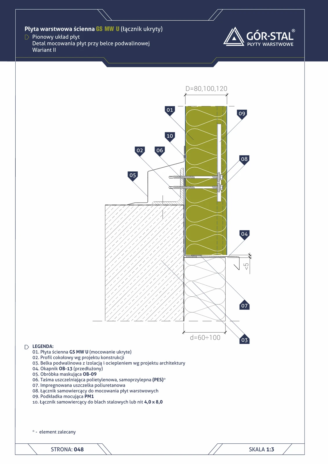
Plinth at sill beam — vertical insPIRe® U panel layout, variant II
Variant II with greater overhang (d=60-100 mm) — for taller premium façades. Identical construction to variant I, longer OB-13.
Plinth at sill beam — horizontal GS MW S/CH panel layout, variant II
Alternative variant with OB-42 starting C-profile + OB-15 drip flashing with OB-15a stiffener (two-piece plinth flashing). Used when the sill beam is narrower or the geometry requires a different flashing than OB-38 + OB-14 from variant I.
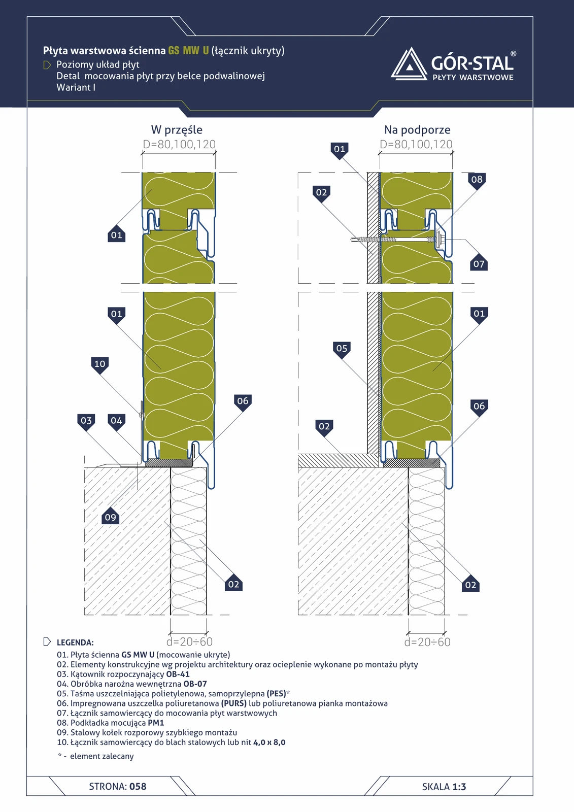
Plinth at sill beam — horizontal GS MW U panel layout, variant I
Premium plinth with concealed fixing in horizontal layout. Variant I (d=20-60 mm) with OB-41 angle as guide for the bottom panel row. PM1 fixing + PES gasket + impregnated PUR seal.
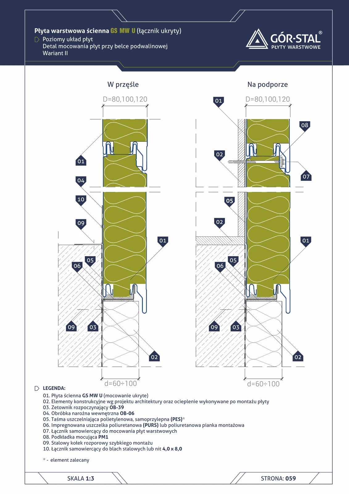
Plinth at sill beam — horizontal GS MW U panel layout, variant II
Variant II of the plinth with greater overhang (d=60-100 mm) and OB-39 Z-profile as a guide. For tall facades and premium installations. OB-06 internal corner flashing, PM1 concealed fastening.
Plinth at sill beam — horizontal GS MW U panel layout, variant III
Variant III of the horizontal plinth with OB-15 drip edge and OB-15a stiffening flashing (d=60-100 mm). The strongest structural performance among plinth variants — the drip edge is stiffened independently of panel thickness. Shown in span and over support.
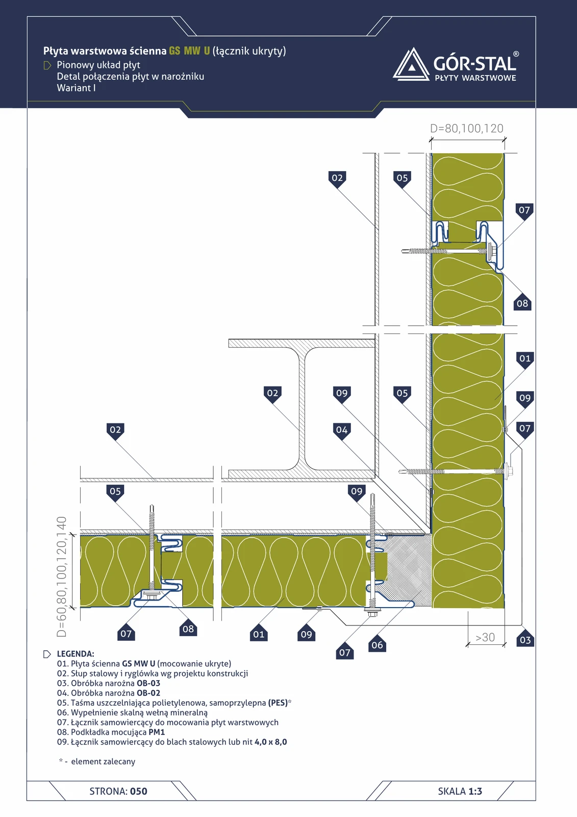
Plinth at sill beam — vertical GS MW U panel layout, variant I
Premium plinth with concealed GS MW U fixing. Variant I (d=20-60 mm) — minimalist drip edge. Fastener hidden in the joint via PM1 washer; OB-09 cover flashing replaces typical OB-08 (geometric difference for U-joint geometry).
Plinth at sill beam — vertical GS MW U panel layout, variant II
Plinth variant II with greater projection (d=60-100 mm) — for taller premium façades and heavier rainfall. Identical construction to variant I (p. 49) with extended OB-13.
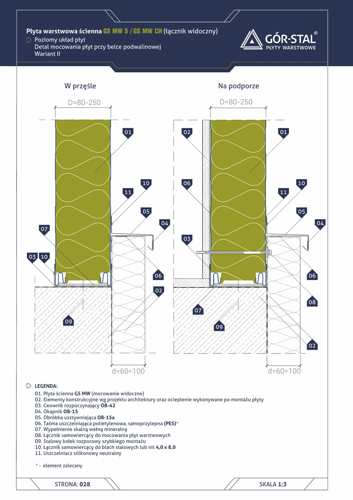
Plinth at sill beam — vertical GS MW S/CH panel layout, variant II
Variant with greater plinth projection (d=60–100 mm) — for tall façades, heavy rain, open terrain with high wind exposure. Identical construction to variant I, but with a longer OB-13 drip flashing.
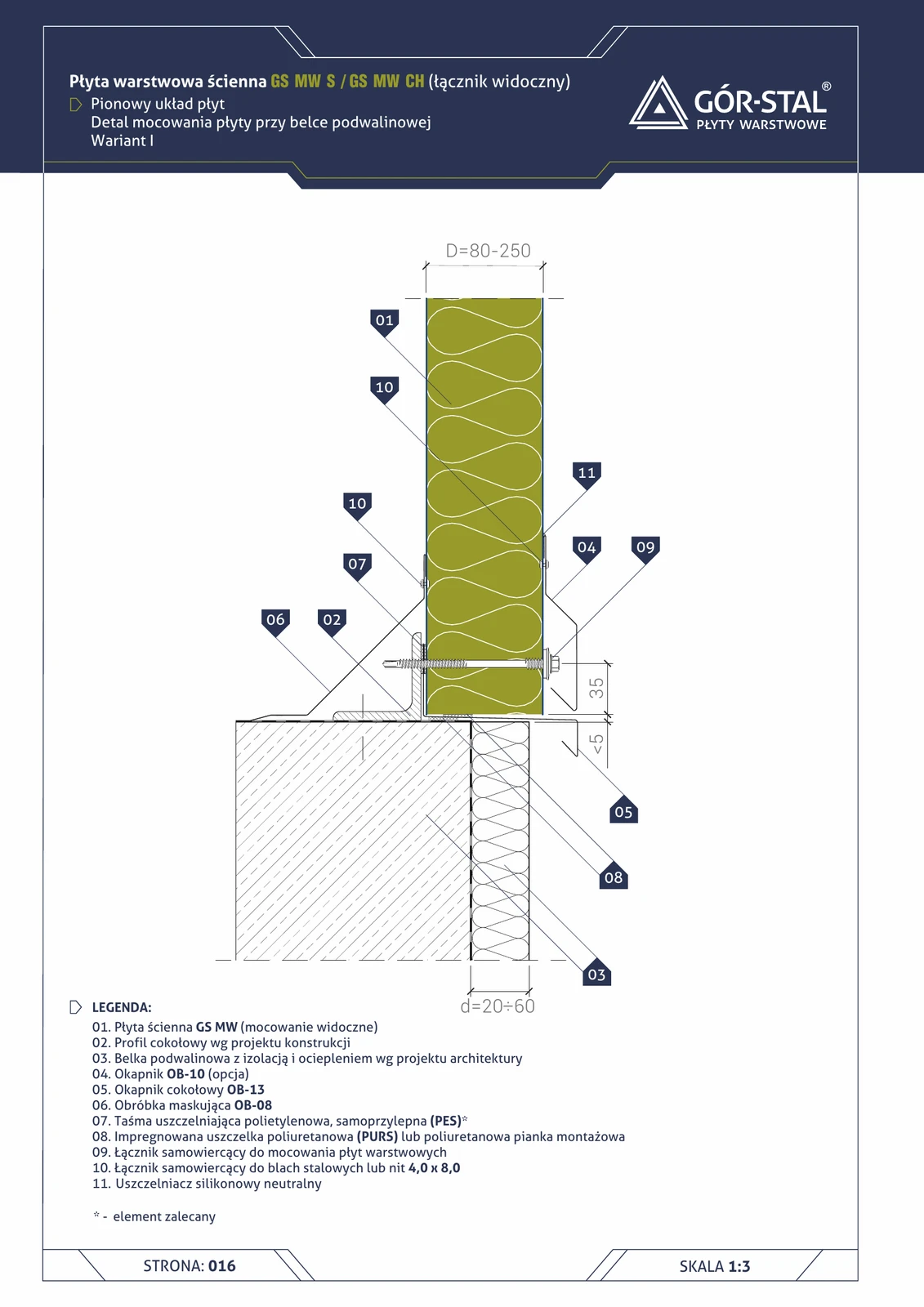
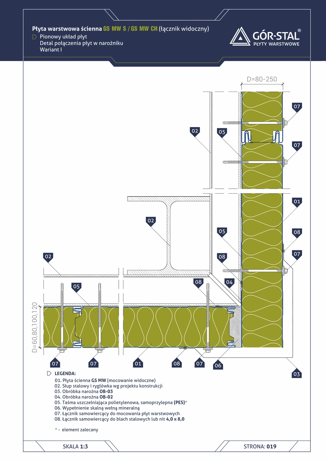
Plinth at sole beam — vertical GS MW S/CH panel layout, variant I
Standard plinth variant with projecting OB-13 drip flashing (depth d=20–60 mm). Vertical layout of GS MW S or CH sandwich panels. OB-10 drip flashing, OB-08 trim flashing inside, PES + neutral silicone seals.
Plinth — GS MW U Sole Beam (horizontal layout)
Plinth junction for mineral wool wall panels in horizontal layout, variant III. OB-41 starter angle + OB-15 drip flashing + OB-15a stiffener. For panels 60-100 mm thick.
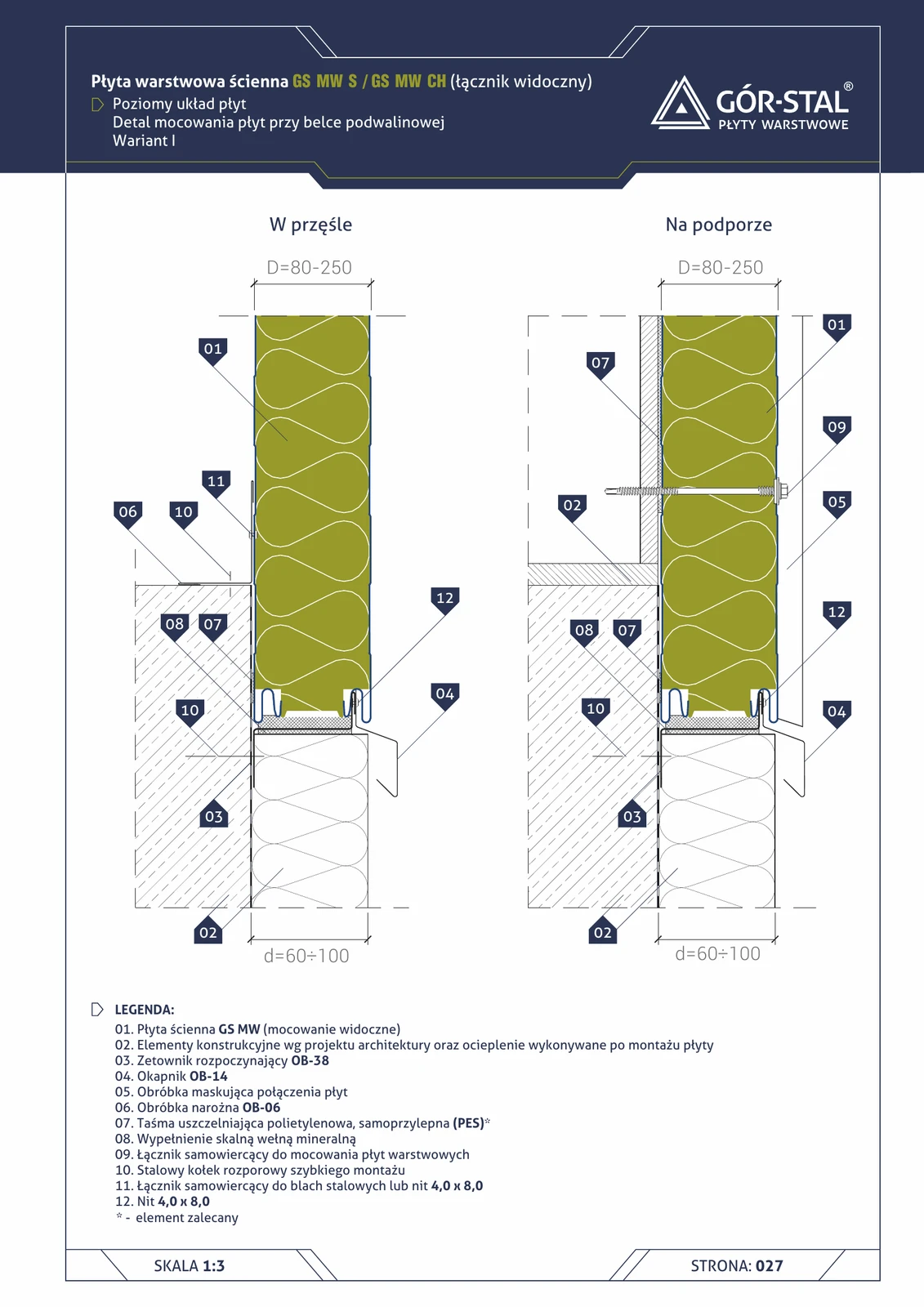
Plinth at sole plate beam — horizontal GS MW S/CH panel layout, variant I
Variant with OB-38 starter Z-profile as guide rail for the bottom row of panels (d=60–100 mm). Unlike the vertical layout (p. 18), the horizontal arrangement requires an OB-38 Z-profile instead of the typical C-profile. OB-14 drip flashing + OB-06 corner.

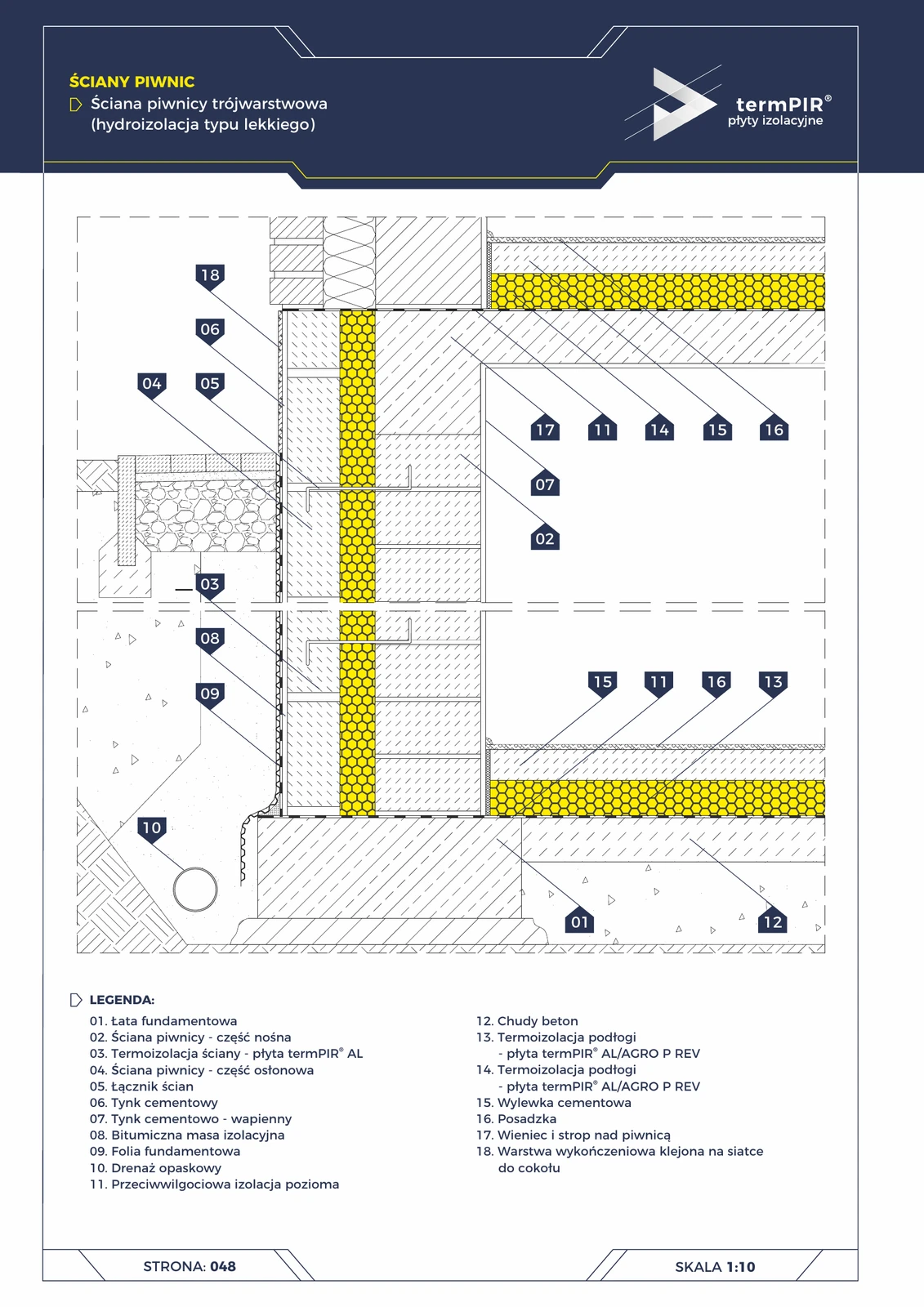
Plinth — 3-layer basement wall — termPIR® AL
Premium cross-section through a basement wall with termPIR® AL insulation in the cavity between two leaves. Light-type waterproofing, perimeter drainage, continuous horizontal DPC at the wall-floor interface.
Protective profiles for CH wall panel (plinth)
Plinth zone of a cold storage wall with **PVC profiles** protecting the lower part of the panel against mechanical damage (forklifts, pallets, equipment). Bumper strip + floor skirting = standard for all cold storage facilities.
Corner (32)
Balcony — ETICS wall — termPIR® ETX
Vertical section of balcony in ETICS wall with termPIR® ETX. Balcony soffit and floor also insulated with PIR. Most commonly used detail in new-generation single-family houses.

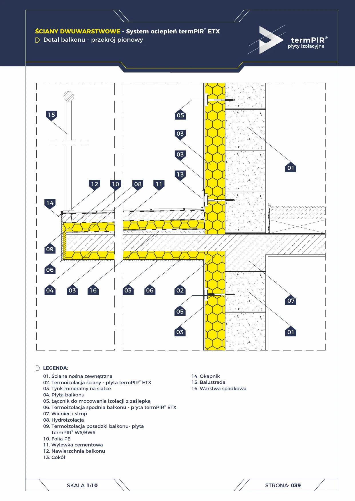
Balcony — three-layer wall — termPIR®
Vertical section of a balcony cantilevering from a three-layer wall. Balcony soffit insulated with termPIR® ETX, floor with termPIR® WS/BWS. Full elimination of the thermal bridge of the RC balcony slab.
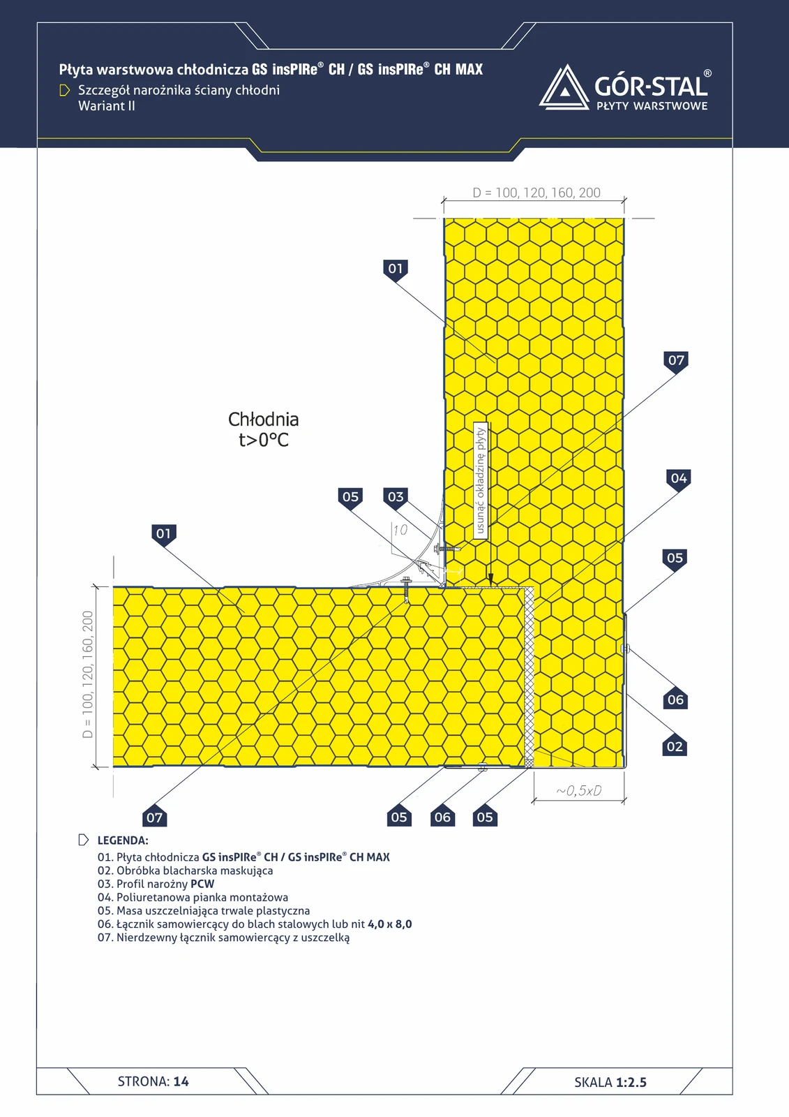
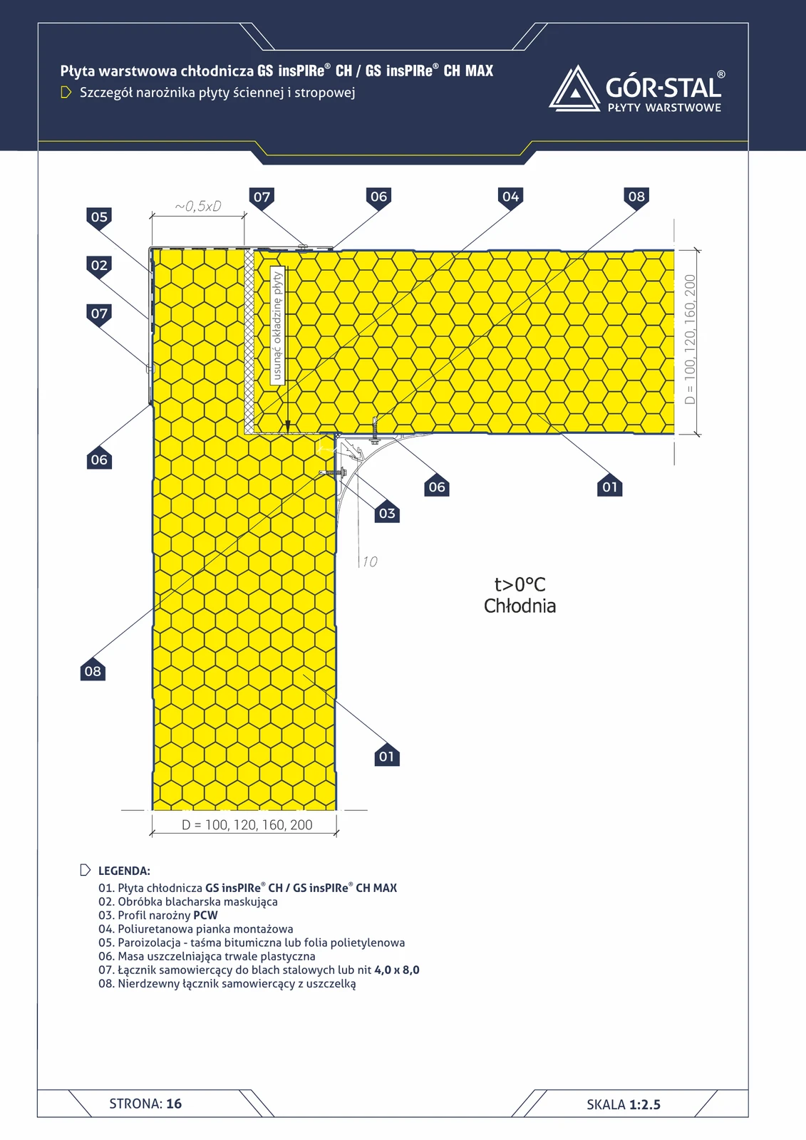
External cold room wall corner — Variant II
Variant II of the cold room corner — panel offset by approx. **0.5×D from the corner** + facing removal within the 0.5×D zone. A less labour-intensive alternative to variant I, better suited for thinner CH panels (80-100 mm).
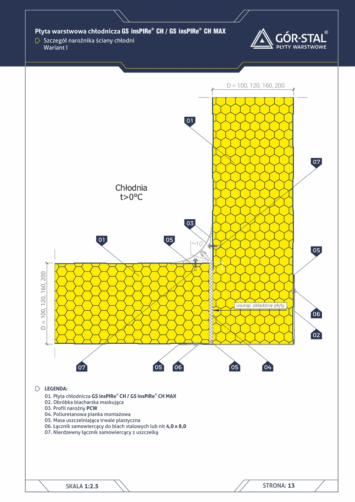
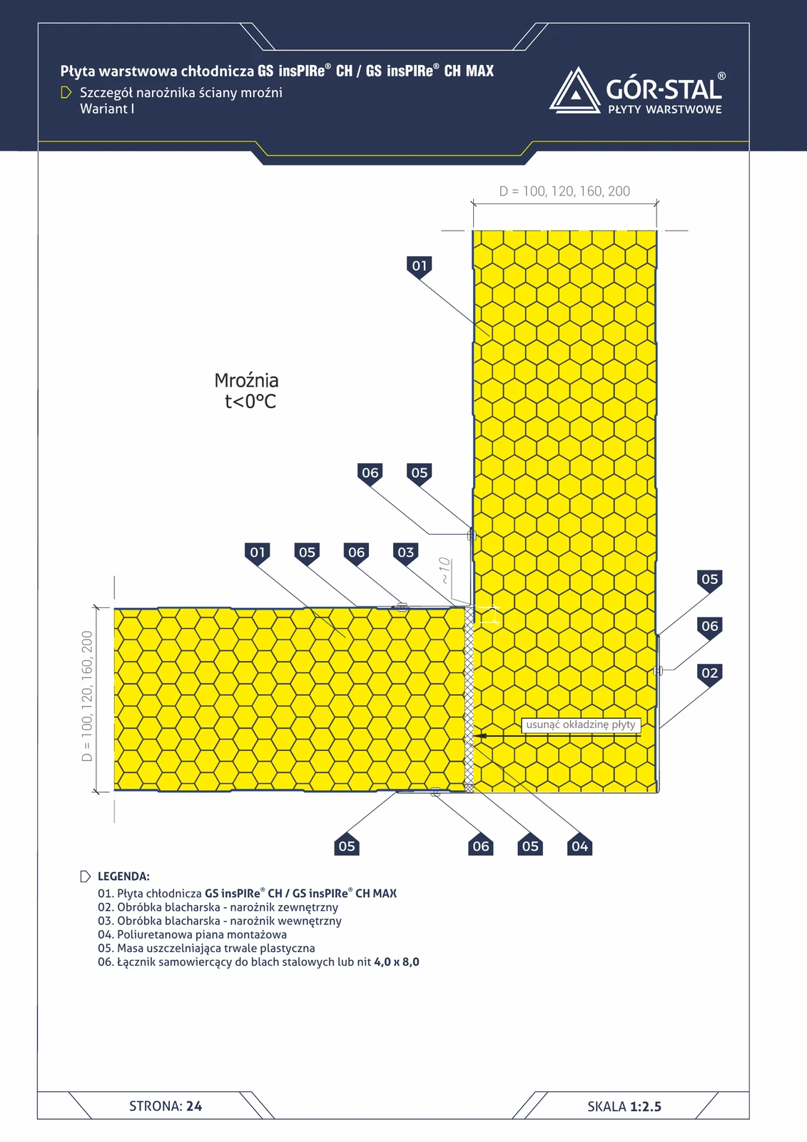
External cold store wall corner — Variant I
External cold store corner (t > 0°C) in variant I — the facing of one panel is **removed in the corner zone**, the joint is sealed with a PVC corner profile + PUR foam + plastic sealant. Stainless fasteners with gasket.
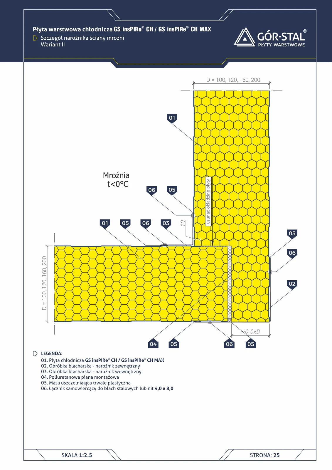
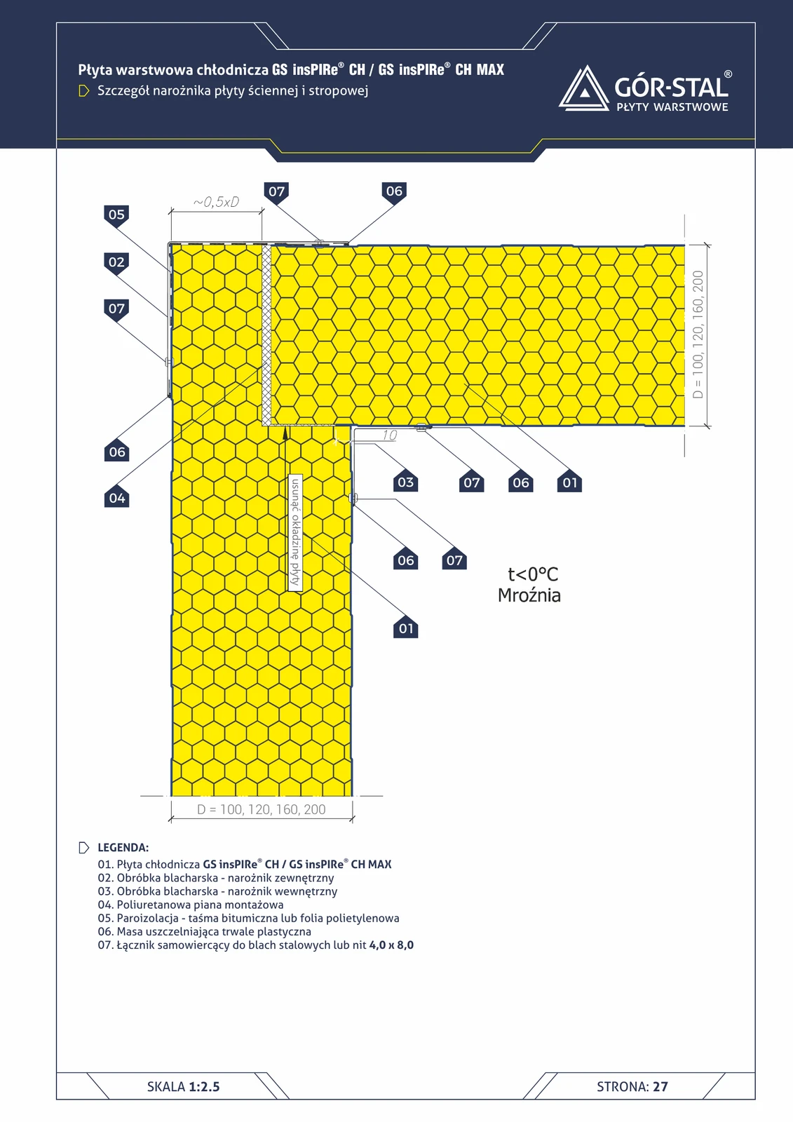
Cold store wall corner — Variant II (t < 0°C)
Variant II of the cold store corner — panel offset by **0.5×D from the corner**. A less labour-intensive alternative to variant I, better suited for thinner CH panels (100-120 mm).
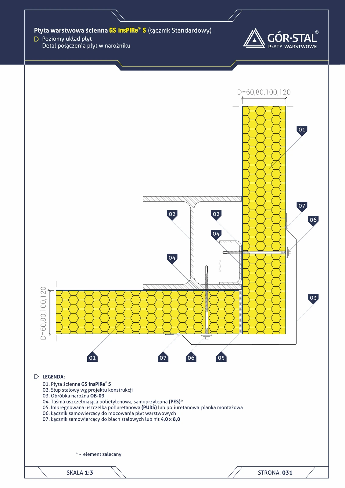
External 90° corner — horizontal insPIRe® S panel layout
Standard rectangular corner in horizontal PIR layout. External OB-03 flashing conceals the joint; expanding foam fills the space at the column.
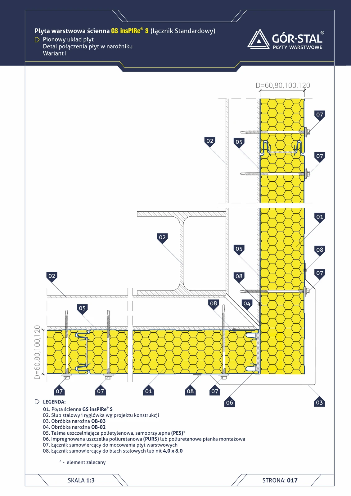
External 90° corner — vertical insPIRe® S panel layout, variant I
Standard rectangular hall corner with vertical PIR panels. OB-03 external + OB-02 internal flashings, installation foam fills the space at the corner column (no mineral wool — PIR is homogeneous and does not require filling).
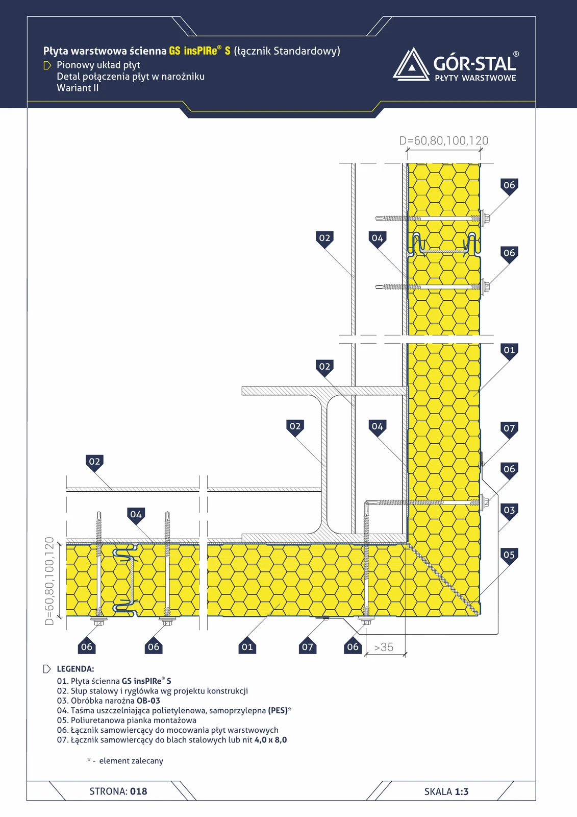
External 90° corner — vertical insPIRe® S panel layout, variant II
Simplified corner variant — external OB-03 flashing only (no internal OB-02). PU foam fills the corner cavity. Suitable for halls with low internal aesthetic requirements.
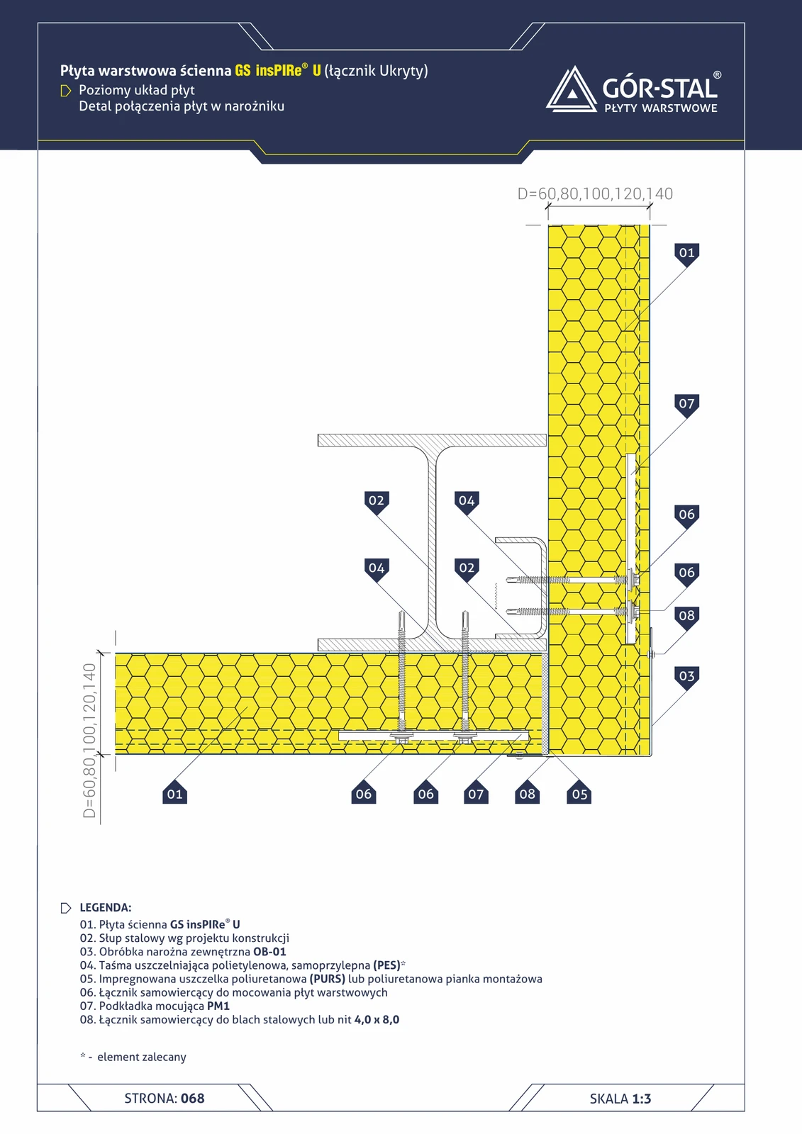
External 90° corner — horizontal insPIRe® U panel layout
Premium rectangular corner in horizontal layout. OB-01 external flashing (differs from OB-03 in S — wider, stiffer for the U joint), PM1 washers.
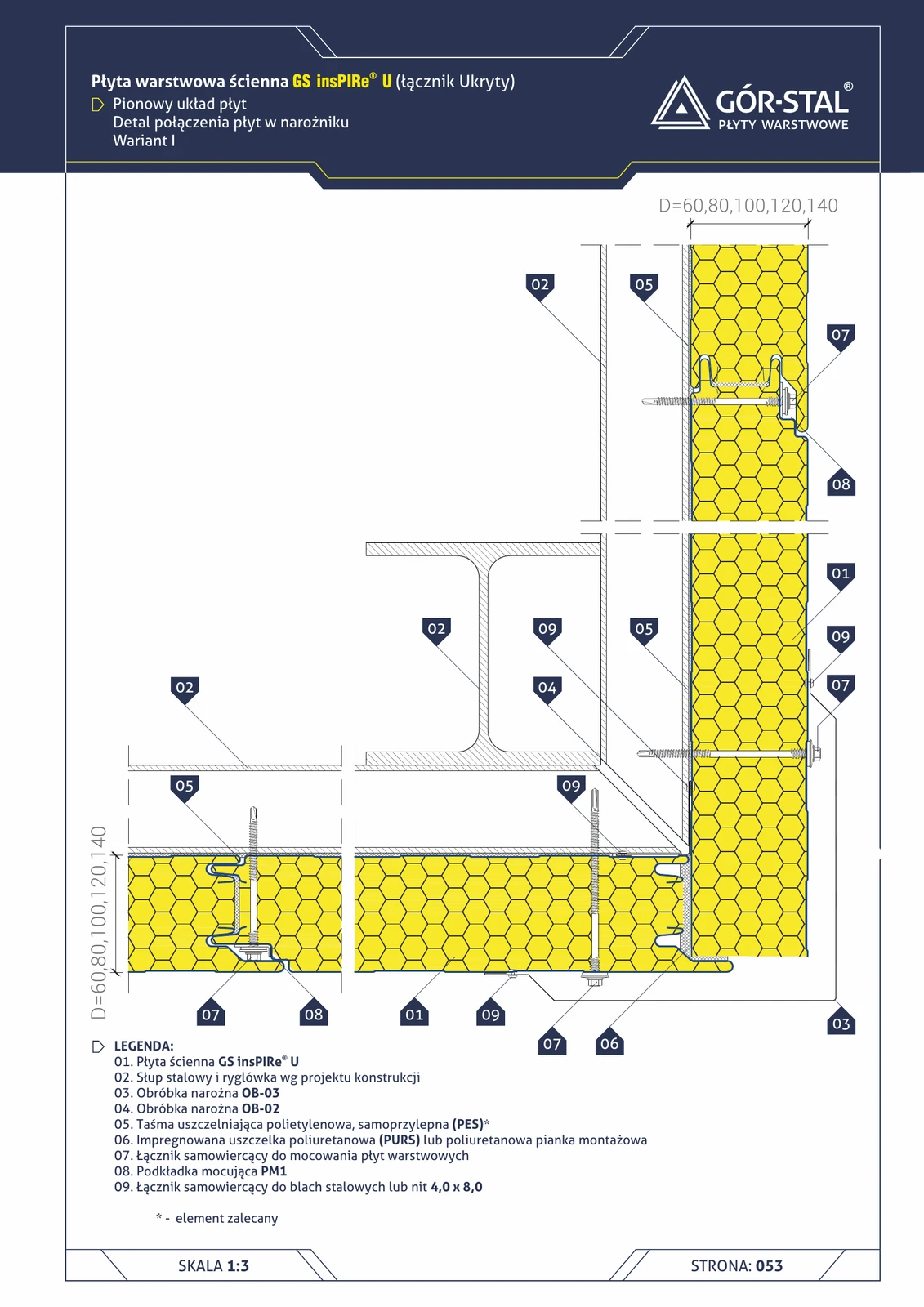
External 90° corner — vertical layout of insPIRe® U panels, variant I
Premium right-angle corner with concealed fastening. OB-03 + OB-02 + PM1 washers. Clean aesthetics with no visible fasteners.
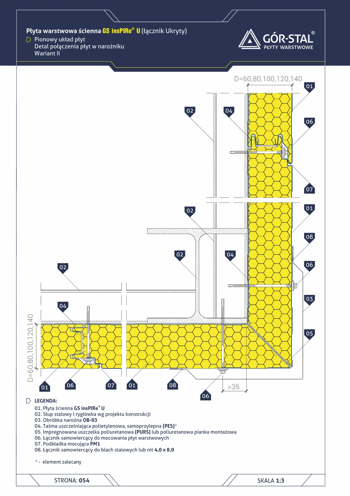
External 90° corner — vertical insPIRe® U panel layout, variant II
Simplified variant of the premium U corner — only external OB-03 (no OB-02). Cheaper, faster installation.
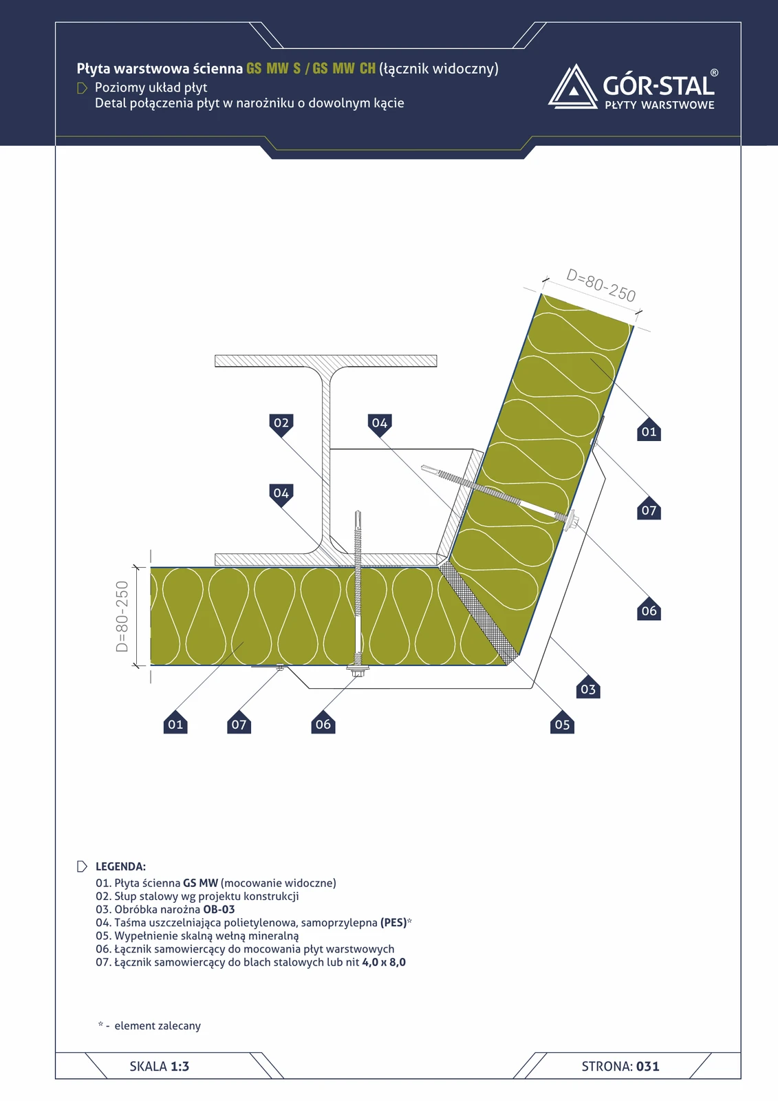
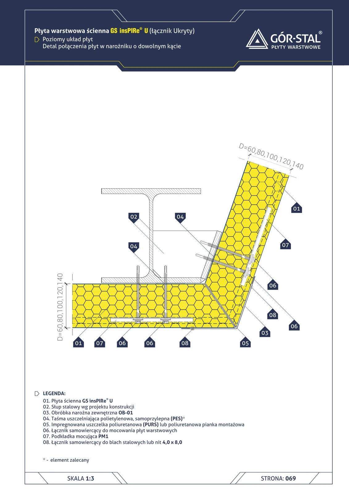
Any-angle corner — horizontal GS MW S/CH panel layout
Variant for non-standard hall geometries with horizontal panel layout. OB-03 corner flashing manufactured individually for the specific angle; construction identical to the 90° corner (p. 32) with adjusted flashing geometry.
Any-angle corner — horizontal insPIRe® U panel layout
Custom-angle corner in premium horizontal PIR layout. Angled OB-01 made to order.
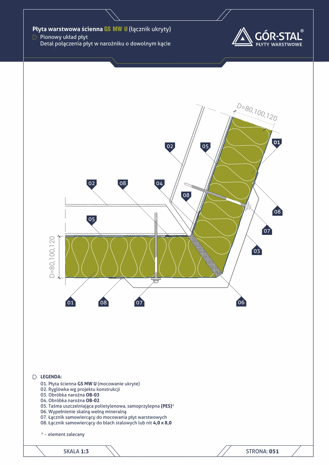
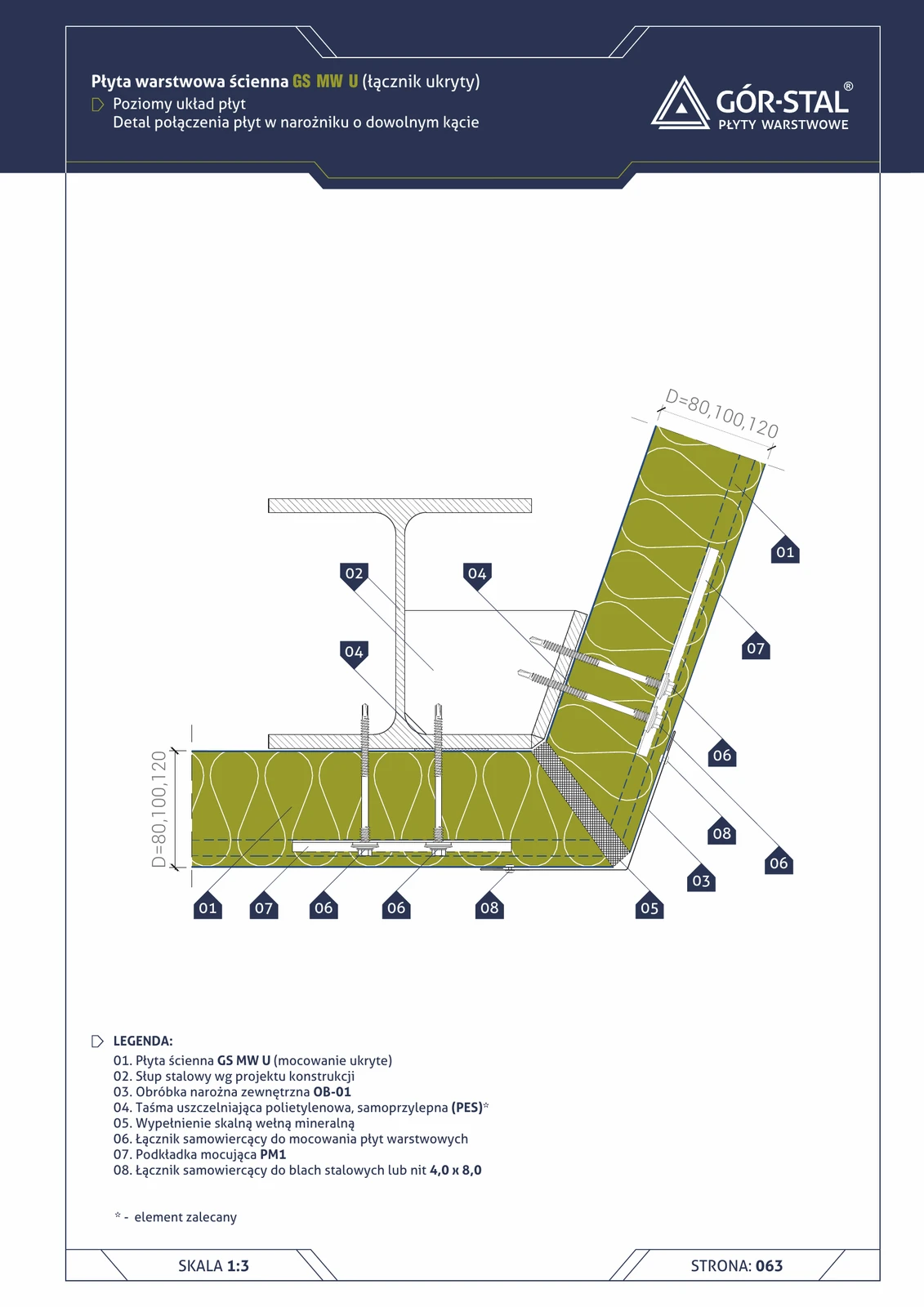
Any-angle corner — vertical layout of GS MW U panels
Non-standard corner at an angle ≠ 90° with premium concealed fixing. OB-02/OB-03 flashings produced individually for a specific angle. Identical logic as in S/CH (p. 22), with concealed fasteners.
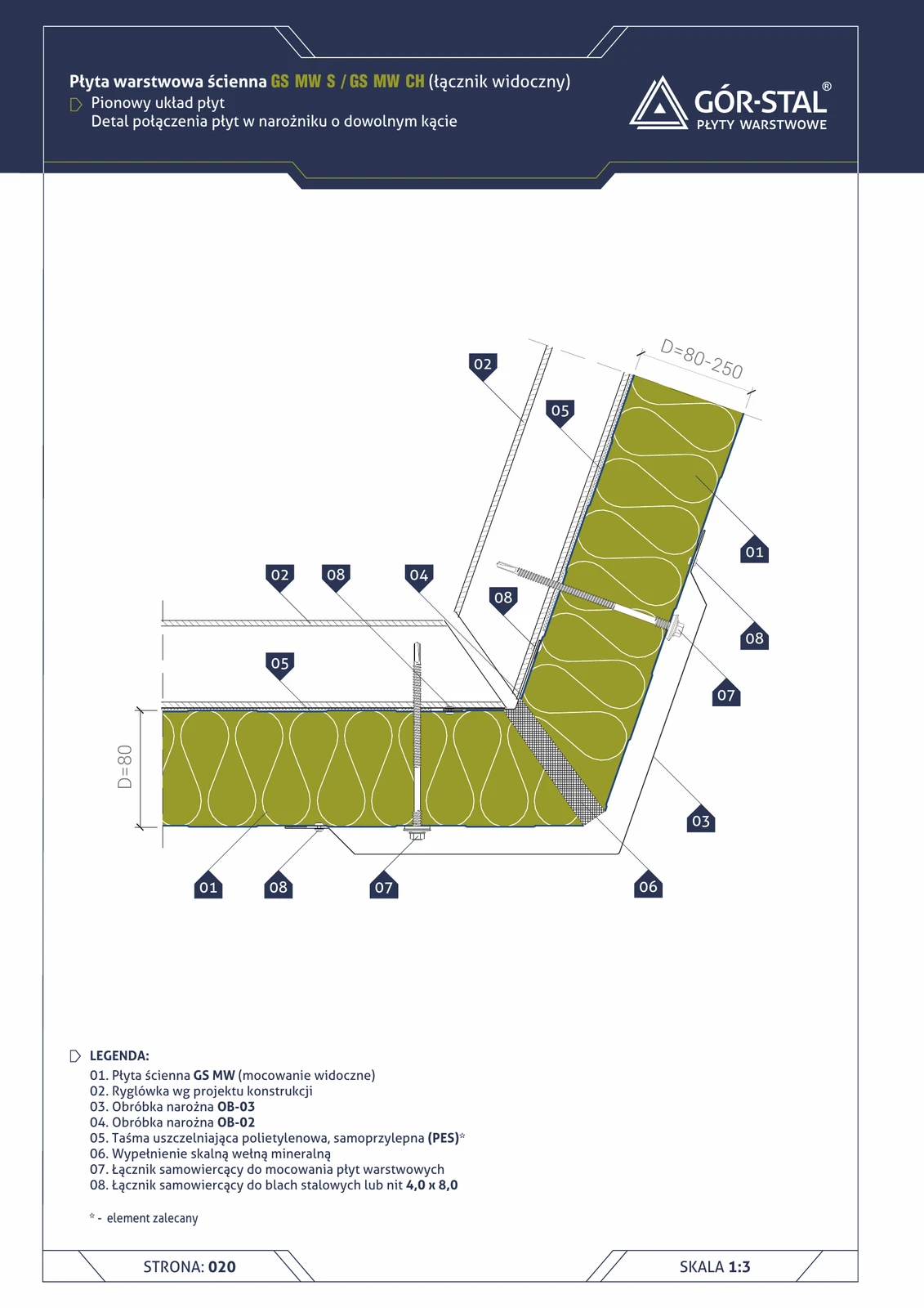
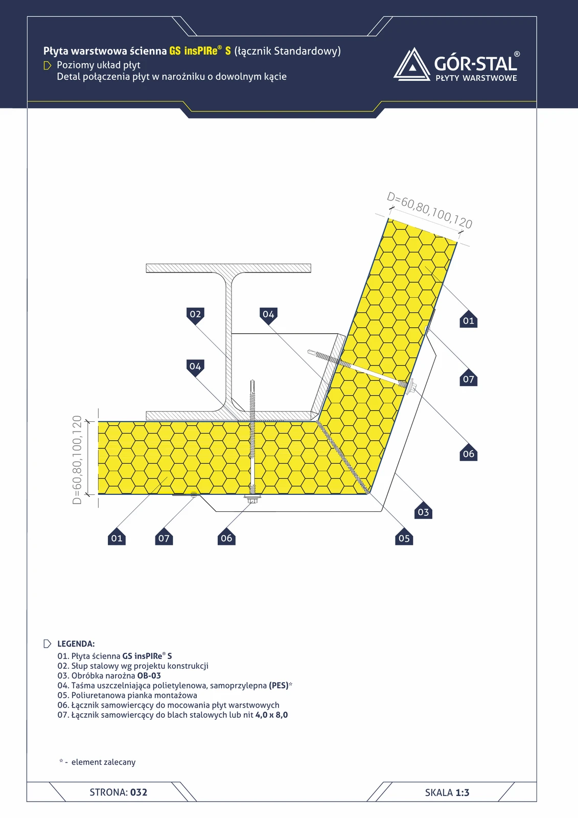
Any-angle corner — vertical GS MW S/CH panel layout
Variant for non-standard hall geometries: corner at an angle other than 90° (e.g. 120°, 135° in buildings with rotundas / polygonal layouts, or an acute angle in halls with aerodynamic geometry). Corner flashings OB-02 / OB-03 angle-adjusted, identical mineral wool infill.
Any-angle corner — vertical insPIRe® U panel layout
Custom-angle corner in premium vertical PIR layout. OB-02/OB-03 flashings made-to-order at required angle.
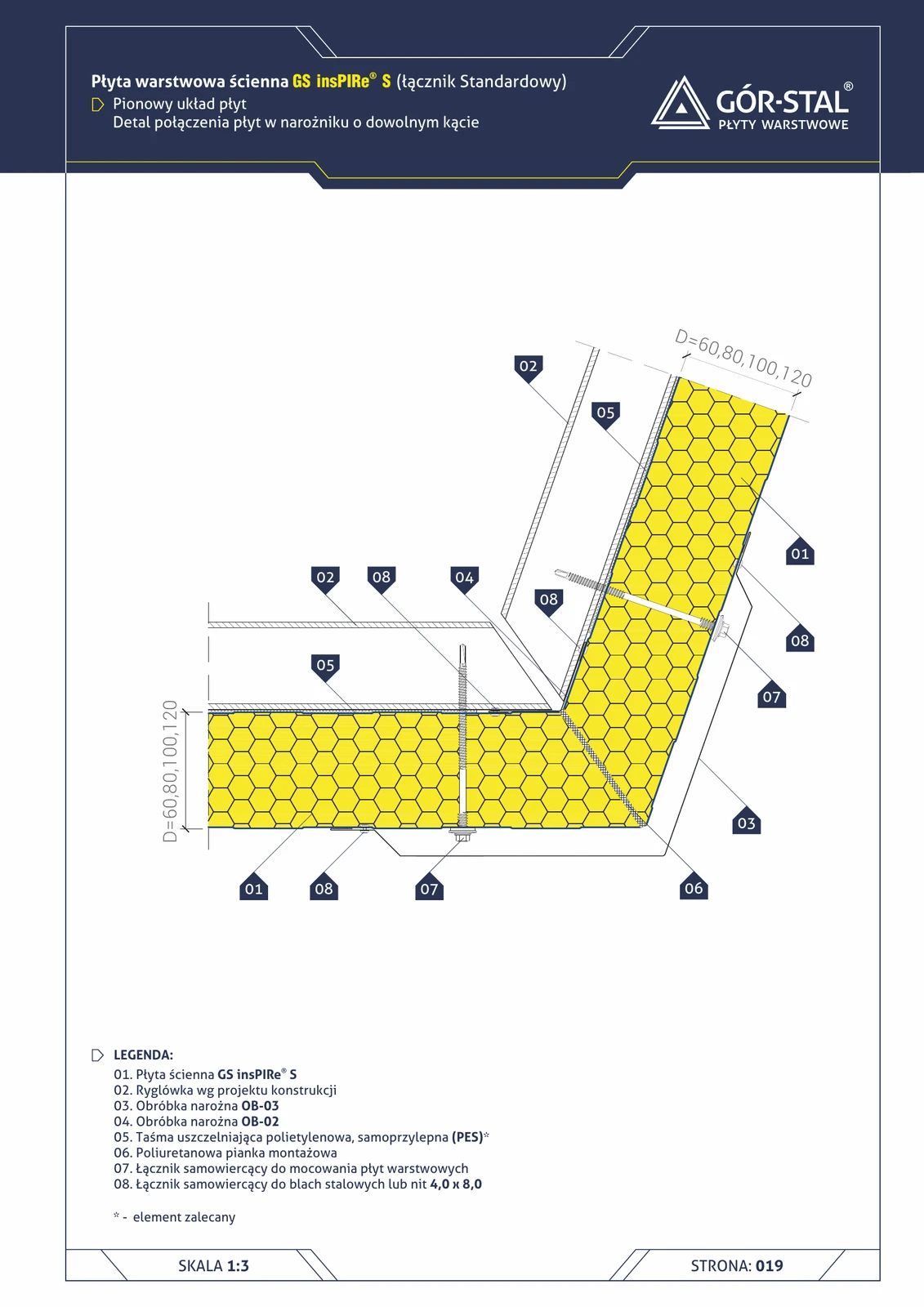
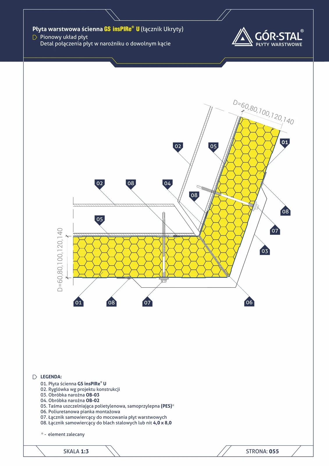
Any-angle corner — vertical insPIRe® S panel layout
Non-standard corner (obtuse 120-150° or acute <90°) for vertical PIR panels. OB-02/OB-03 flashings custom-made to the specific angle; assembly foam fills the cavity.
Custom angle corner — horizontal GS MW U panel layout
Non-standard corner (≠90°) in premium horizontal GS MW U. OB-01 angular flashing custom-made, same logic as 90° corner (p. 64).
Custom-angle corner — horizontal layout of insPIRe® S panels
Non-standard corner in horizontal PIR layout. OB-03 manufactured to order for the required angle; PU foam fills the void at the post.
Over-rafter pitched roof — corner with gable wall
Junction detail of pitched roof in over-rafter system with vertical gable wall. Continuous termPIR® AL insulation from roof onto gable wall — elimination of thermal bridge in 3D corner.
Wall and ceiling panel corner — cold store
Corner junction of vertical wall panel + horizontal ceiling panel in cold store (t > 0°C). Wall facing **removed within the 0.5×D zone**, vapour barrier with bituminous tape / PE film, PVC profile + PUR foam + permanently plastic sealant.
Wall and ceiling panel corner — freezer (t < 0°C)
Corner junction of vertical wall panel + horizontal ceiling panel in a freezer. **Vapour barrier in the corner zone** is critical; OB-01 + OB-02 + 3-layer sealing.
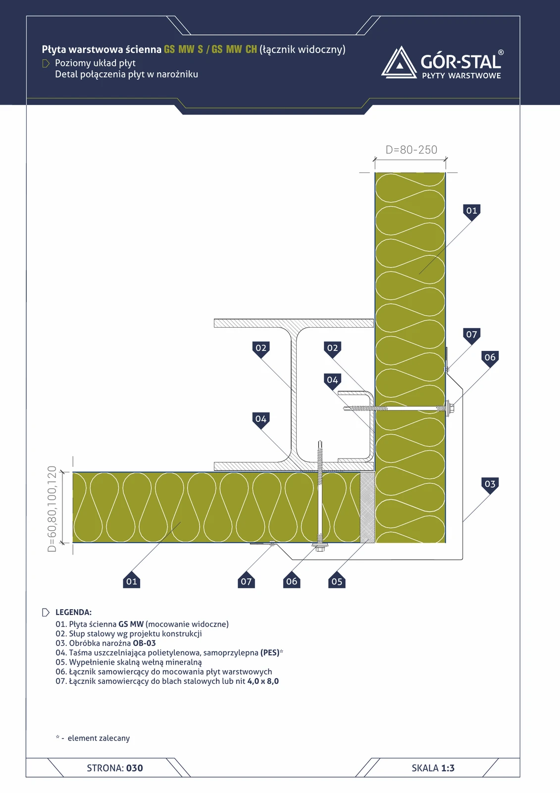
External corner 90° — horizontal GS MW S/CH panel layout
Classic rectangular hall corner with horizontal panel layout. Simpler geometry than the vertical layout — only external OB-03 flashing (no OB-02), mineral wool fills the space at the corner column.
External corner 90° — horizontal GS MW U panel layout
Premium rectangular corner in horizontal arrangement. External OB-01 flashing (differs from OB-03 used for S/CH — wider, stiffer to suit U-lock geometry), PM1 washers at fixings.
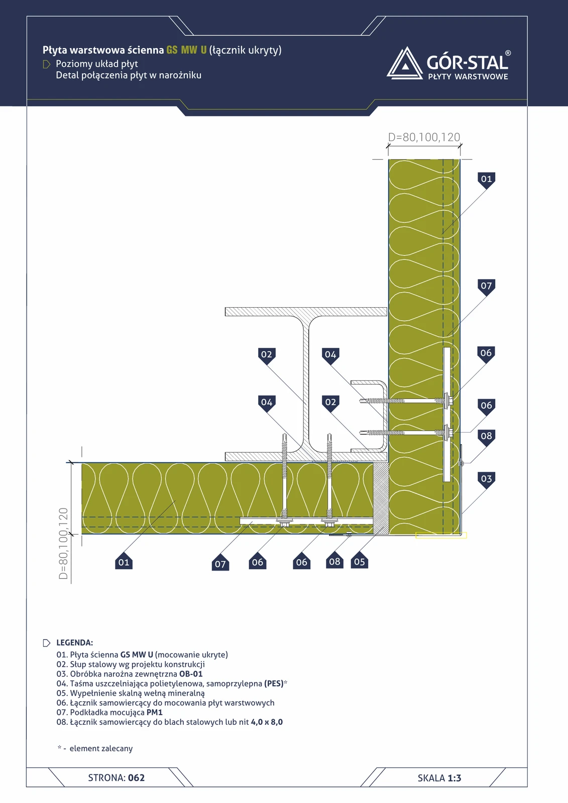
External corner 90° — vertical GS MW U panel layout (variant I)
Premium right-angle corner with concealed fixing. GS MW U panels terminate at the corner column, with mineral wool between panels and column. OB-02/OB-03 flashings + PM1 washer — same logic as S/CH (p. 21), differing aesthetically through the absence of visible fasteners.
90° external corner — vertical layout of GS MW S/CH panels (variant I)
Classic rectangular corner of an industrial hall — two walls meeting at 90°. Vertical GS MW sandwich panels terminate at the corner column; OB-03 corner flashing conceals the joint from outside, OB-02 from inside, with the cavity filled with mineral wool.
Freezer wall corner — Variant I (t < 0°C)
Freezer corner variant I — facing of one panel removed in the corner zone, **OB-01 external corner + OB-02 internal corner flashing**. Vs cold store: more stringent sealing.
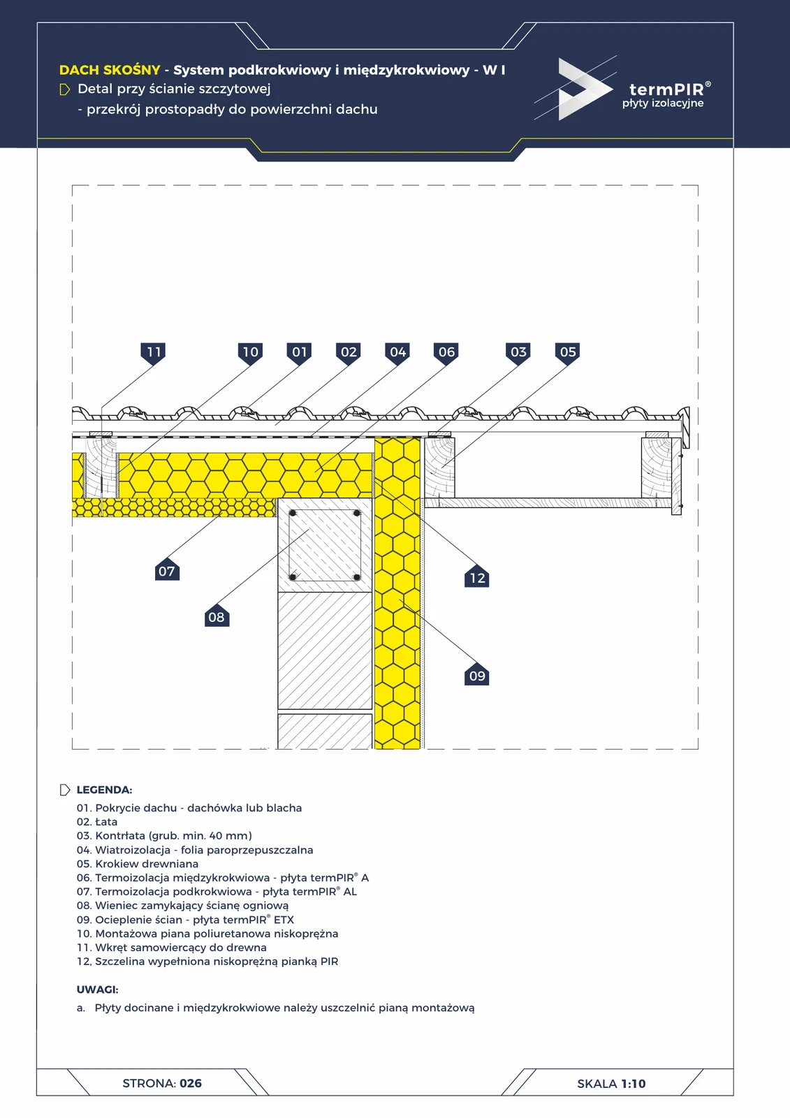
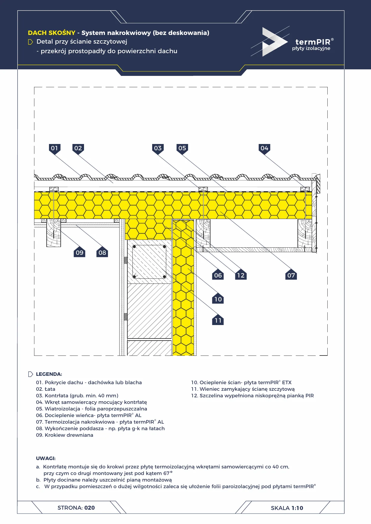
Gable wall — W1 under-rafter roof (termPIR® ETX + AL)
Junction between a W1 pitched roof and a fire gable wall (e.g. semi-detached / terraced house). Requires 3 separate elements: fire-resistant ring beam in the wall + ETX façade insulation + continuity of termPIR AL roof insulation. All sealed with tapes and low-expansion PIR foam.
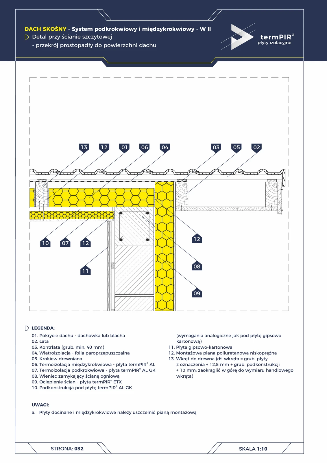
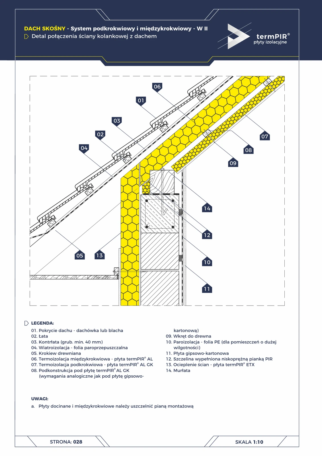
Gable wall — under-rafter roof W2 (termPIR® AL GK + ETX)
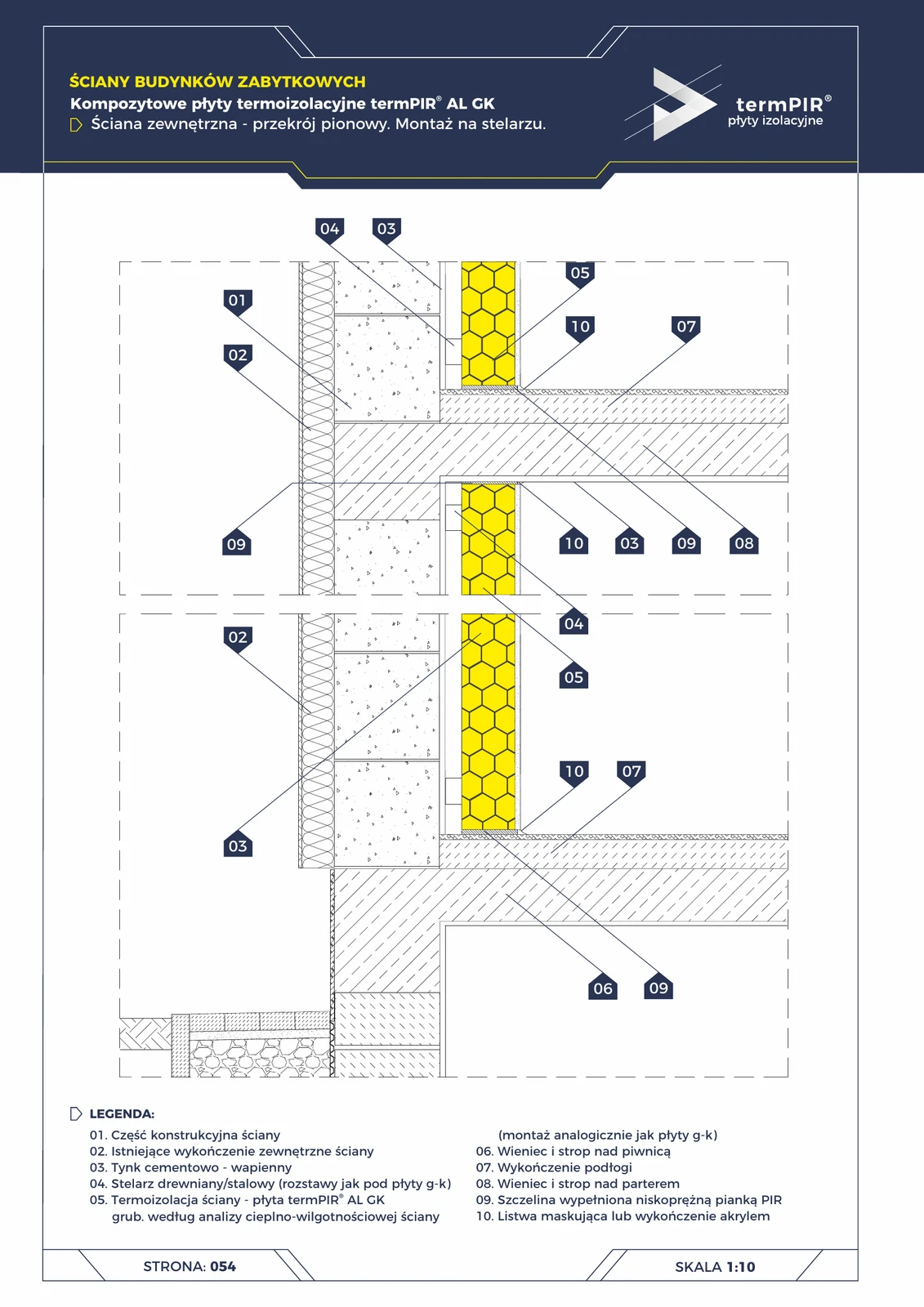
Variant II of the fire gable wall detail (semi-detached / terraced houses). With termPIR® AL GK composite board as the under-rafter layer — faster finishing + classic REI 60-120 from the ETX system on the wall.
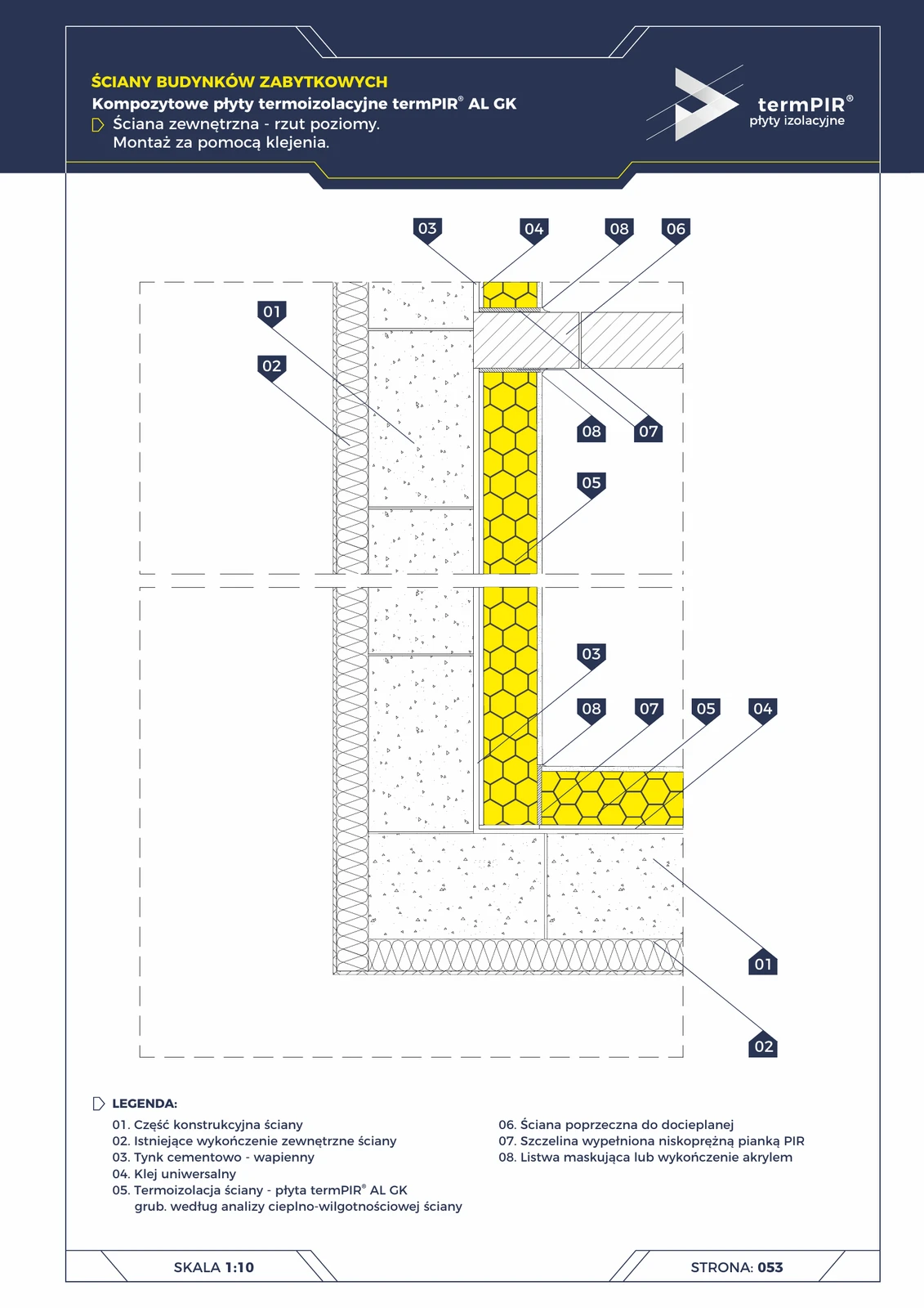
Heritage wall AL GK — glued installation (horizontal section)
Horizontal view of internal insulation. Corner detail with perpendicular transverse wall (e.g. partition wall). Critical expansion gap filled with low-expansion PIR foam, concealed with trim or acrylic.
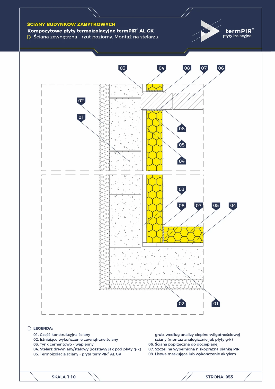
Historic wall AL GK — frame mounting (horizontal section)
Horizontal view of frame-mounted insulation from inside. Corner detail with transverse wall — critical PIR foam compensation joint + cover strip. Timber or CD60 frame around the corner perpendicular to the wall.
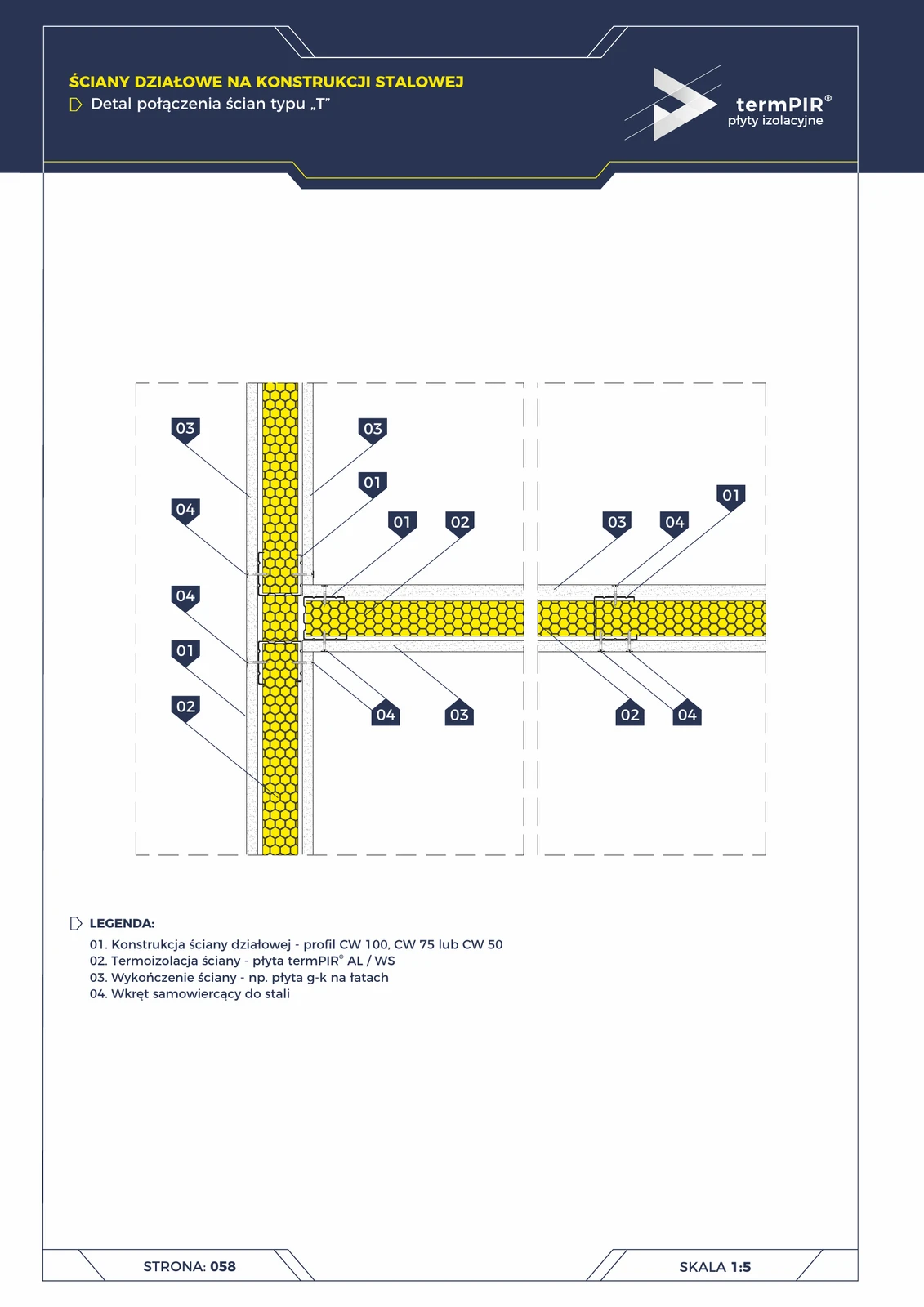
Partition walls — T-junction
Meeting of two partition walls at 90° (e.g. separating a niche, walk-in closet, bathroom). CW profiles joined with screws; termPIR® AL insulation continued in both directions. Characteristic of modern open-space layouts.
Window opening (37)
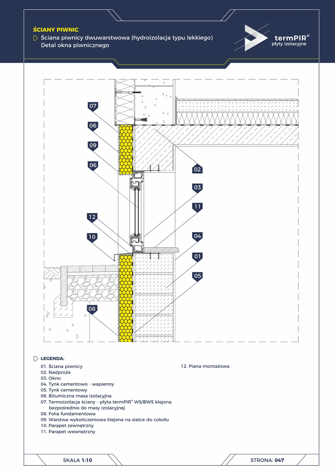
Basement window — two-layer basement wall (termPIR® WS)
The most demanding window installation in the entire house: below grade, in a damp environment. WS insulation around the frame + tight low-expansion foam sealing + absolutely sloped external sill for water drainage. Without perfection = leakage.
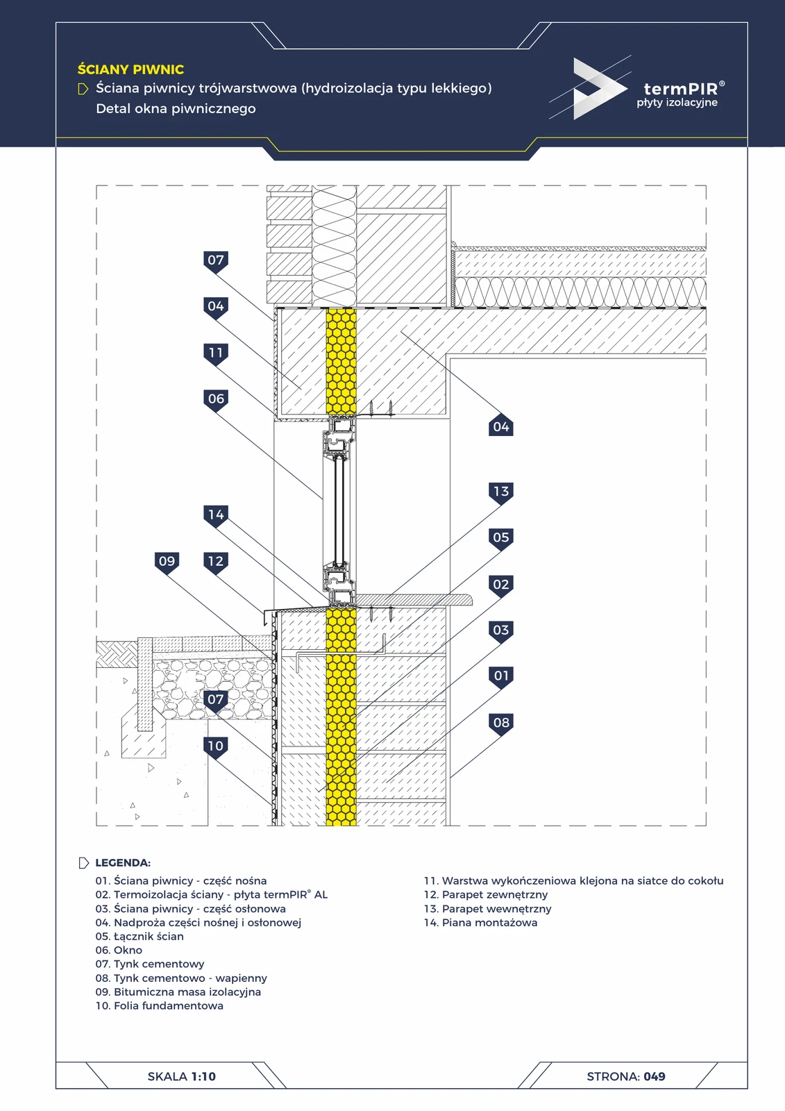
Basement window — three-layer basement (termPIR® AL)
Vertical installation of a basement window in a three-layer wall. Requires two lintels: in the load-bearing part and in the clinker facing. A termPIR® AL strip above the facing eliminates the linear thermal bridge. Low-expansion foam + vapour-tight tape.
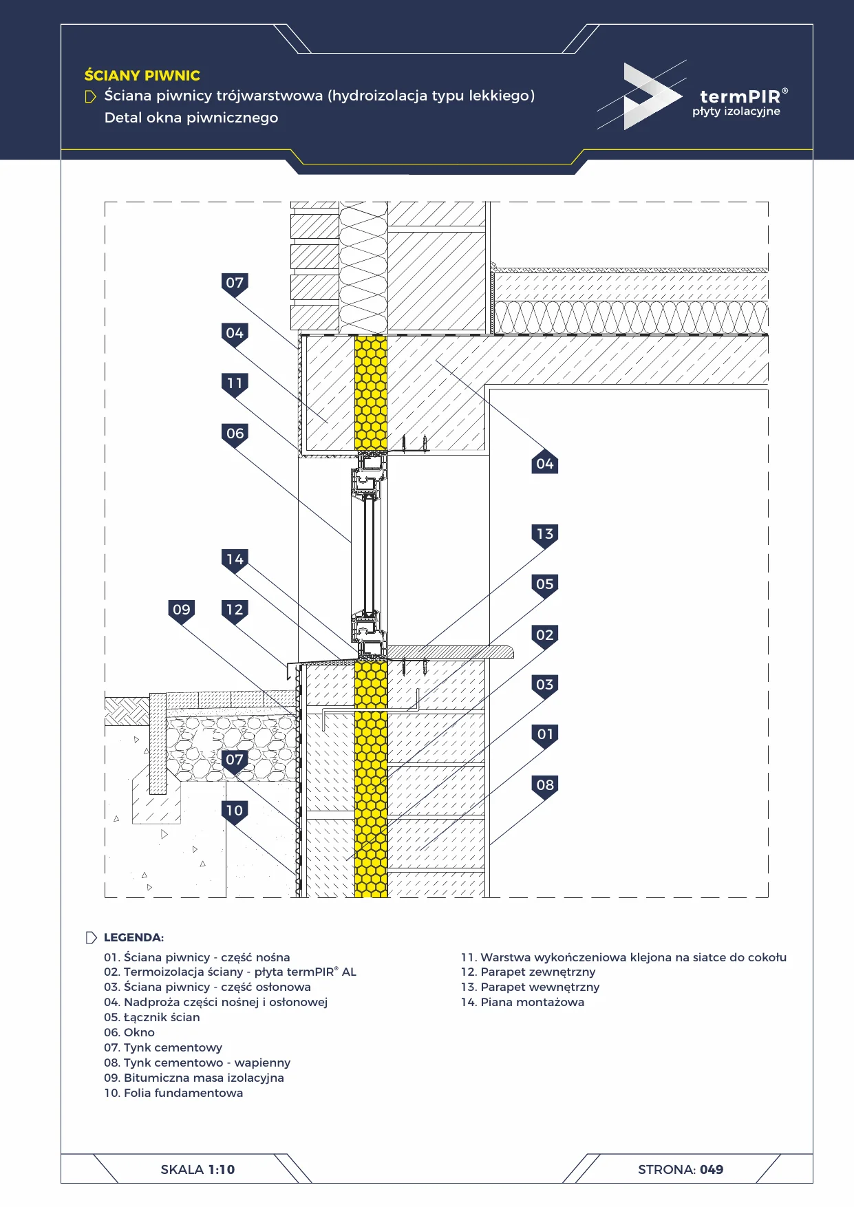
Basement window — 3-layer wall — termPIR® AL
Window installation in a three-layer basement wall. Rainwater drainage well, waterproofing around the frame perimeter, termPIR® AL continuity around the frame in the wall cavity.
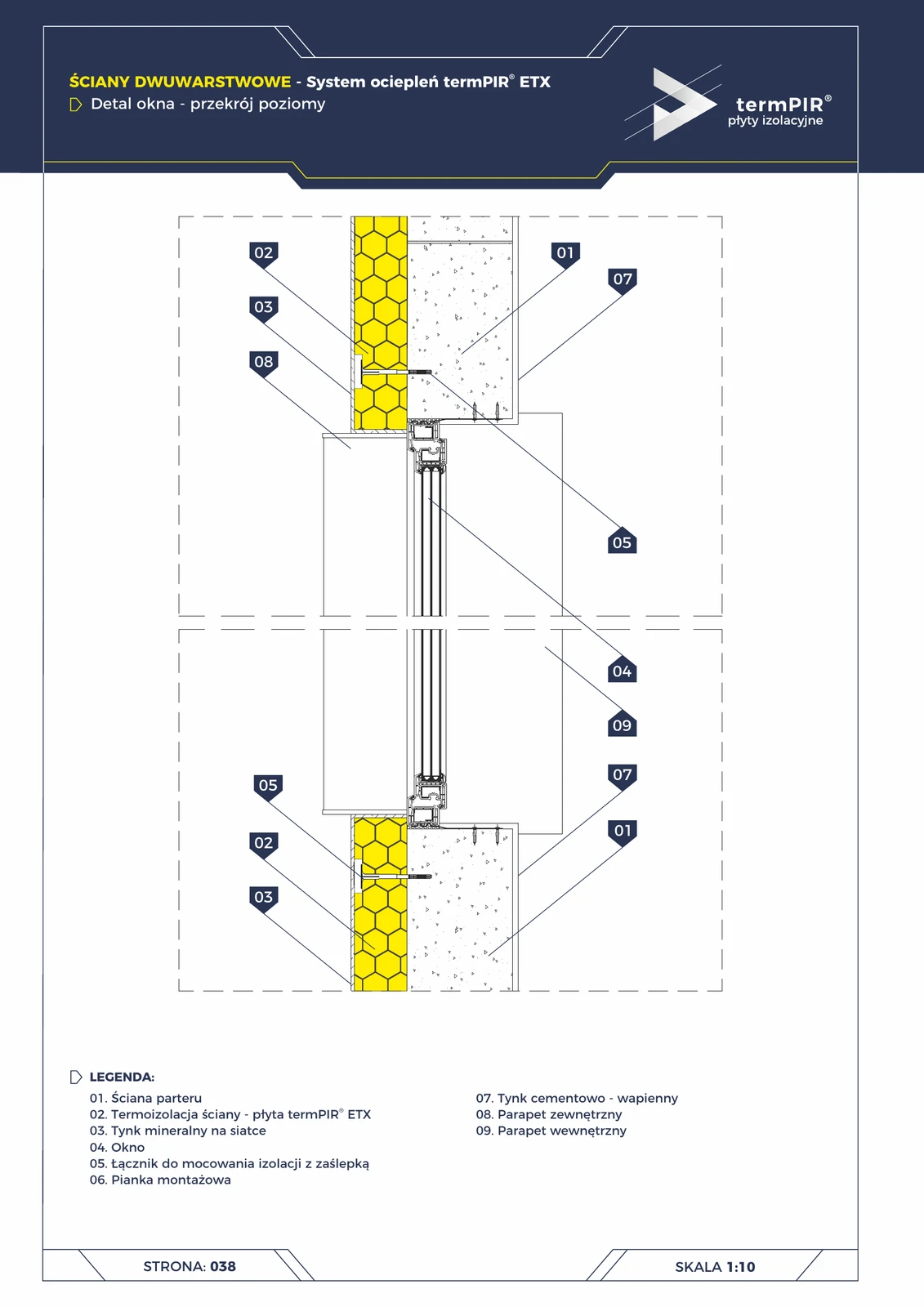
Window in ETICS termPIR® ETX — horizontal section
Horizontal window installation detail: critical continuity of termPIR® ETX on the side reveals + sealing with low-expansion foam. Eliminates the linear thermal bridge ψ ≈ 0.4 W/m·K that occurs when the frame is not insulated.
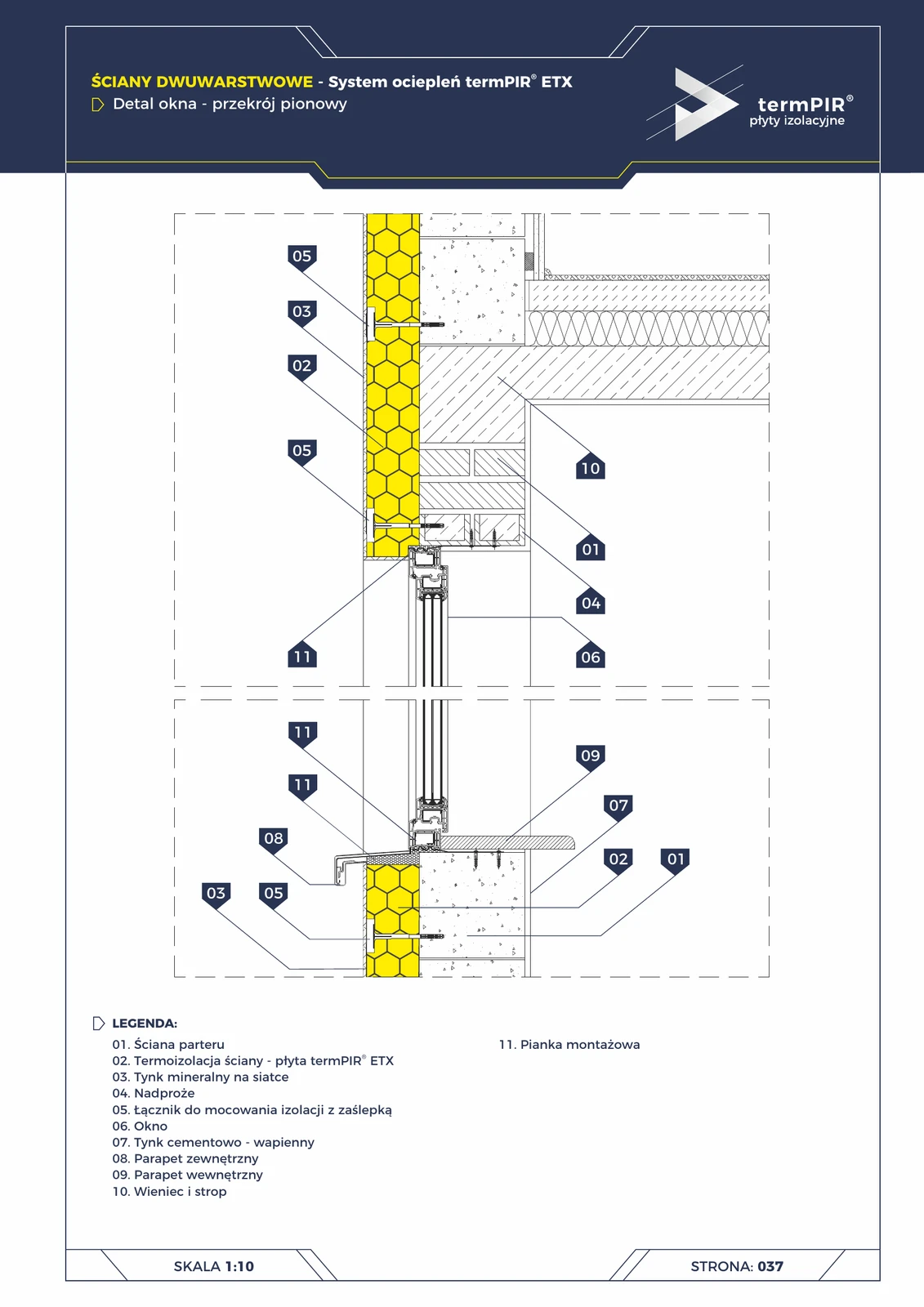
Window in ETICS termPIR® ETX — vertical section
Vertical detail of window installation in a two-layer wall with ETICS termPIR® ETX. Critical elements: lintel insulation, ETX insulation continuity around the frame perimeter, external sill with 30 mm drip edge + sealing with low-expansion foam.
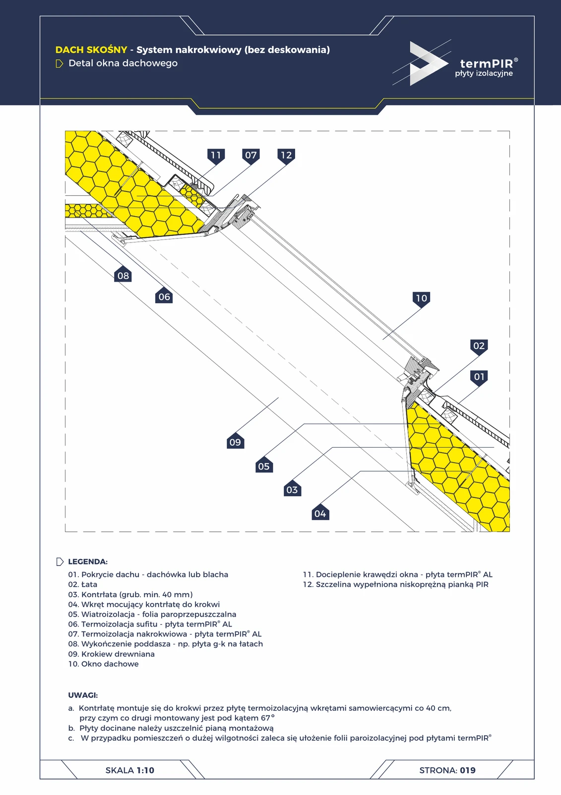
Roof window — over-rafter roof (termPIR® AL)
The most common thermal bridge in pitched roofs: the roof window edge. Without frame insulation = condensation on the reveal in winter. Solution: additional termPIR® AL board insulating the edge + low-expansion PIR foam in the gap between frame and rafter.
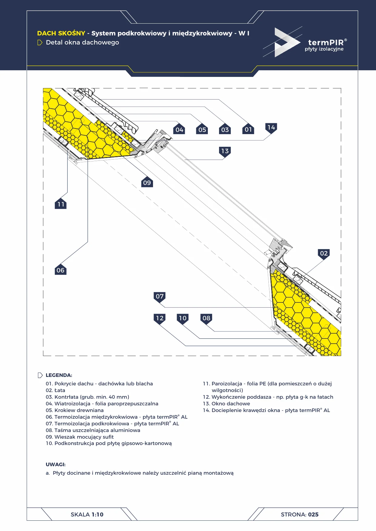
Roof window — under-rafter system W1
Roof window installation (Velux / FAKRO / Roto) in the under-rafter and between-rafter W1 system. termPIR® AL insulation routed around the window frame for full thermal continuity.
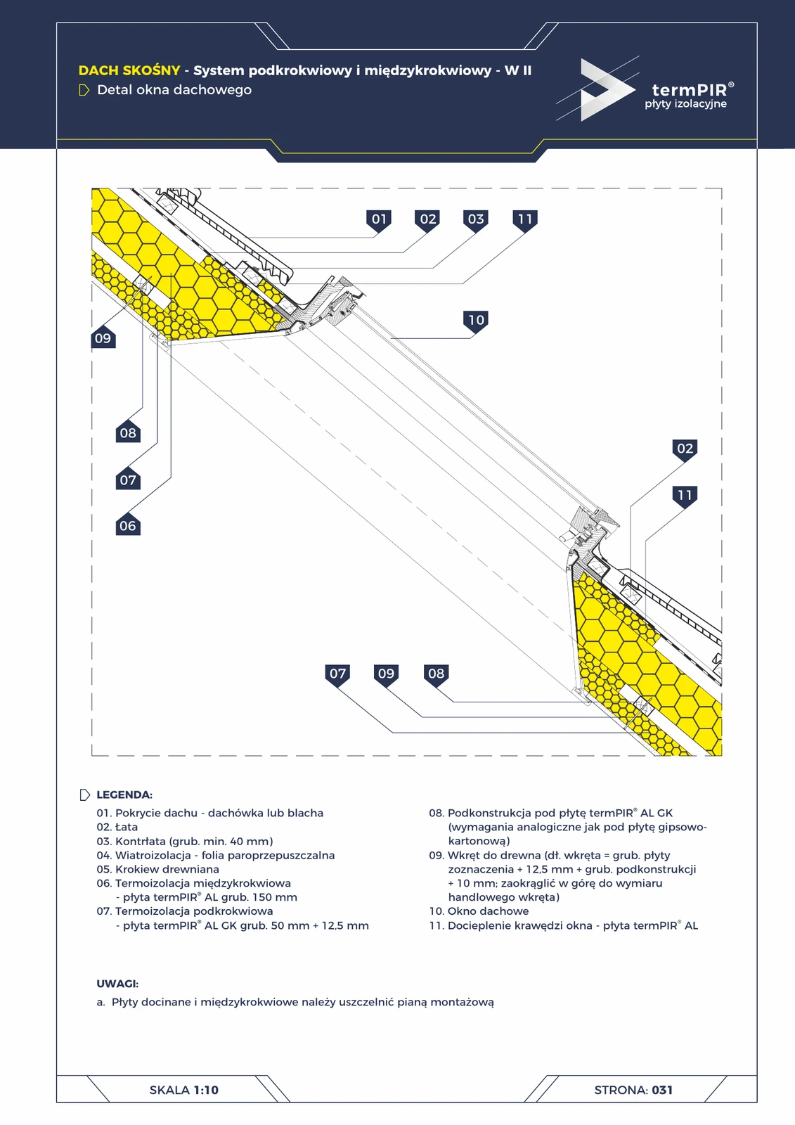
Roof window — under-rafter W2 roof (termPIR® AL + AL GK)
Roof window installation detail in the W2 system. Two-layer thermal insulation: 150 mm termPIR® AL between rafters + 50 mm AL GK with plasterboard under rafters. Window edge additionally insulated with termPIR® AL board.
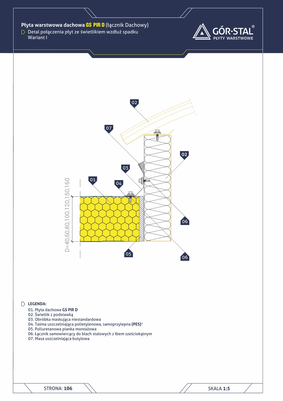
Skylight — side along slope, variant I (GS PIR D)
Detail of side connection between skylight and roof slope, variant I. Skylight runs along the slope (side edge), custom cover flashing.
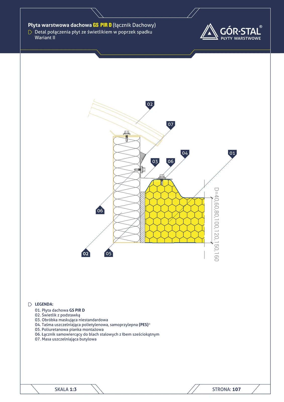
Skylight — lateral along slope, variant II (GS PIR D)
Variant II of lateral skylight connection along the slope — alternative flashing solution vs variant I.
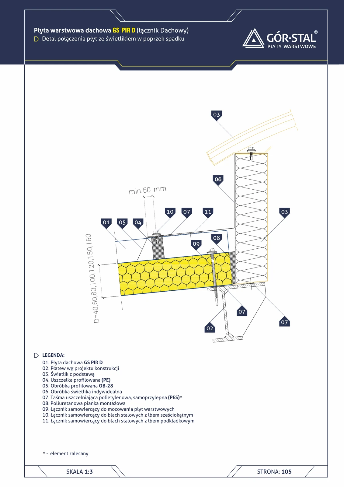
Roof skylight — perpendicular to slope (GS PIR D)
Detail of roof panel connection with a skylight **perpendicular to the slope** (skylight runs across the width of the roof, perpendicular to the slope). Profiled flashing OB-28 + custom skylight flashing + profiled PE gasket.
Industrial window — horizontal GS MW S/CH panel layout (vertical section)
Vertical window detail in a hall with horizontal sandwich panels. Identical flashing set as in the vertical layout (p. 27): OB-10/OB-13 drip flashings above the window, OB-37 sill + OB-16 stiffener below the window.
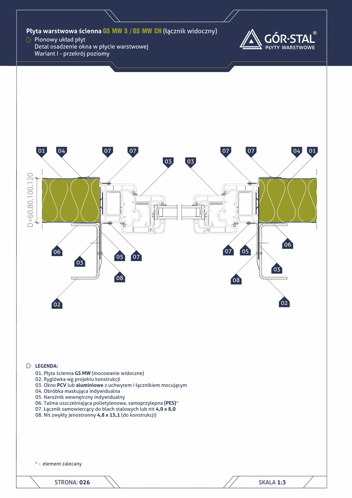
Industrial window — horizontal GS MW S/CH panel layout (horizontal section)
Horizontal detail of window junction — top view. Window side jamb with custom flashings and internal corners. Identical composition as the vertical layout (p. 28).
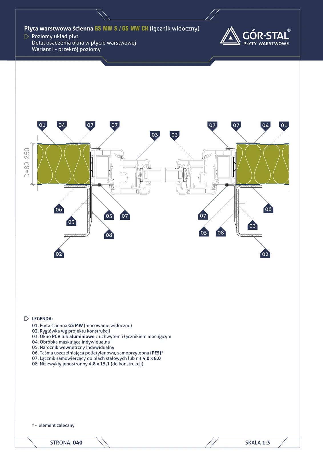
Industrial window — vertical GS MW S/CH panel layout (horizontal section)
Horizontal detail of the window junction — top view. Side window reveal with custom masking flashings and internal corner pieces. Window frame fixed with blind rivets to the sub-framing, sealed with PES tape + neutral silicone.
Industrial window — horizontal GS MW U panel layout (horizontal section)
Horizontal detail of window junction — top view, premium concealed fastening. Window side jamb with custom flashings, corners, PM1 washers.
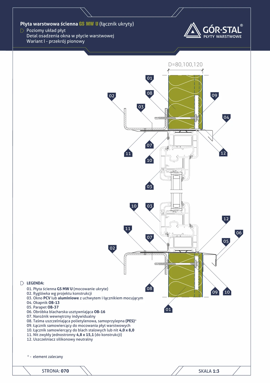
Industrial window — horizontal GS MW U panel layout (vertical section)
Vertical window detail in an industrial hall with premium horizontal GS MW U panels. The OB-13 drip flashing + OB-37 sill + OB-16 stiffener composition is identical to the vertical U layout (p. 58).
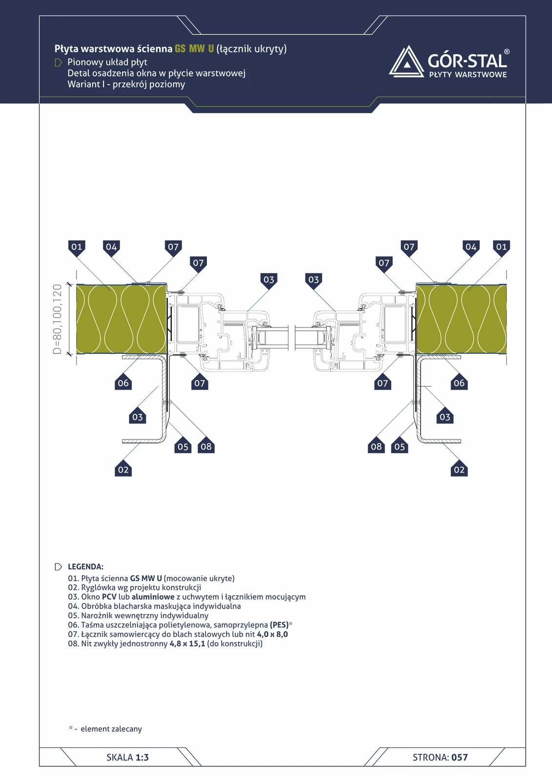
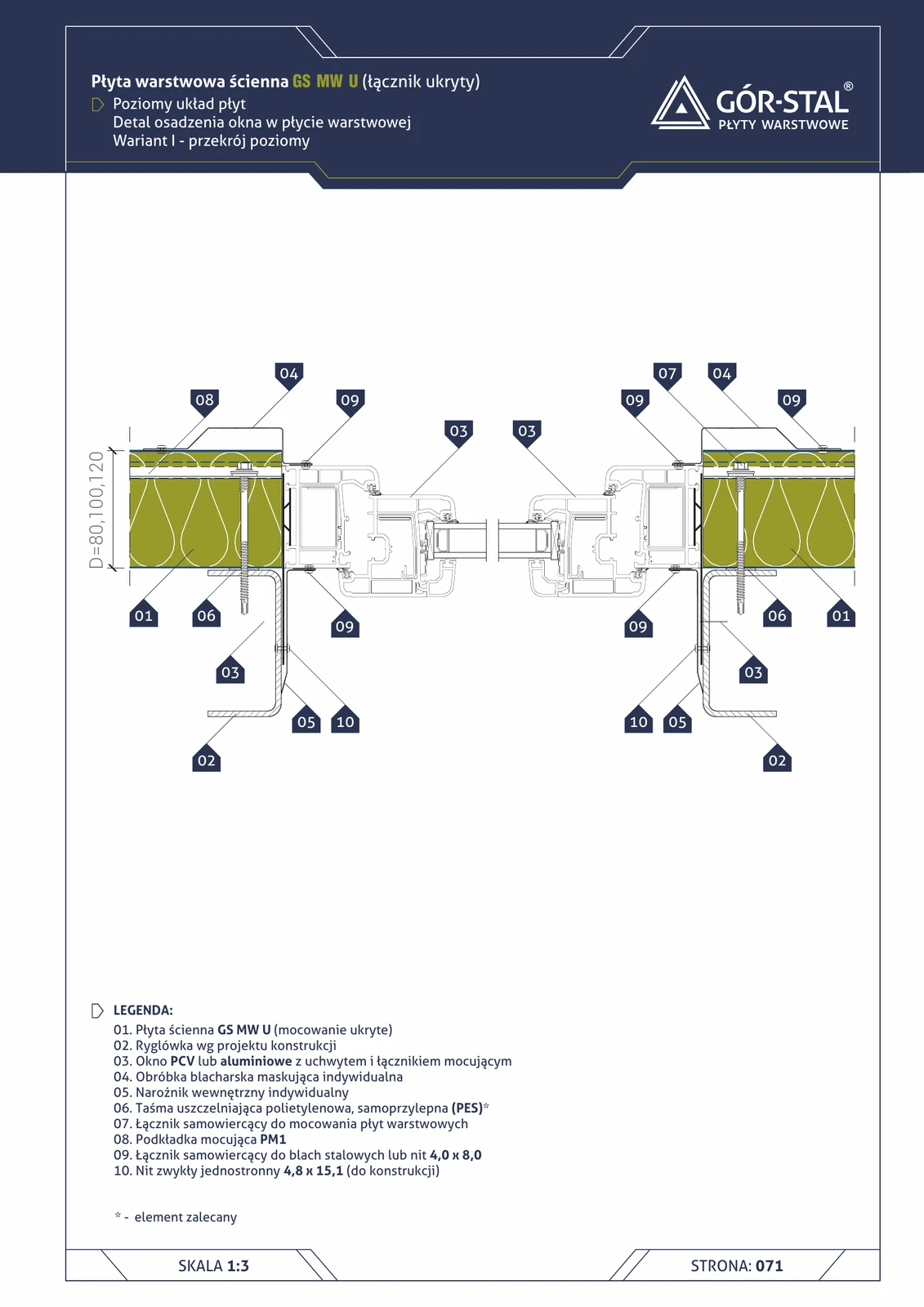
Industrial window — vertical GS MW U panel layout (horizontal section)
Horizontal detail of window junction — top view, premium concealed fastening. Custom side flashings, internal corners. Window frame fixed with blind rivets.
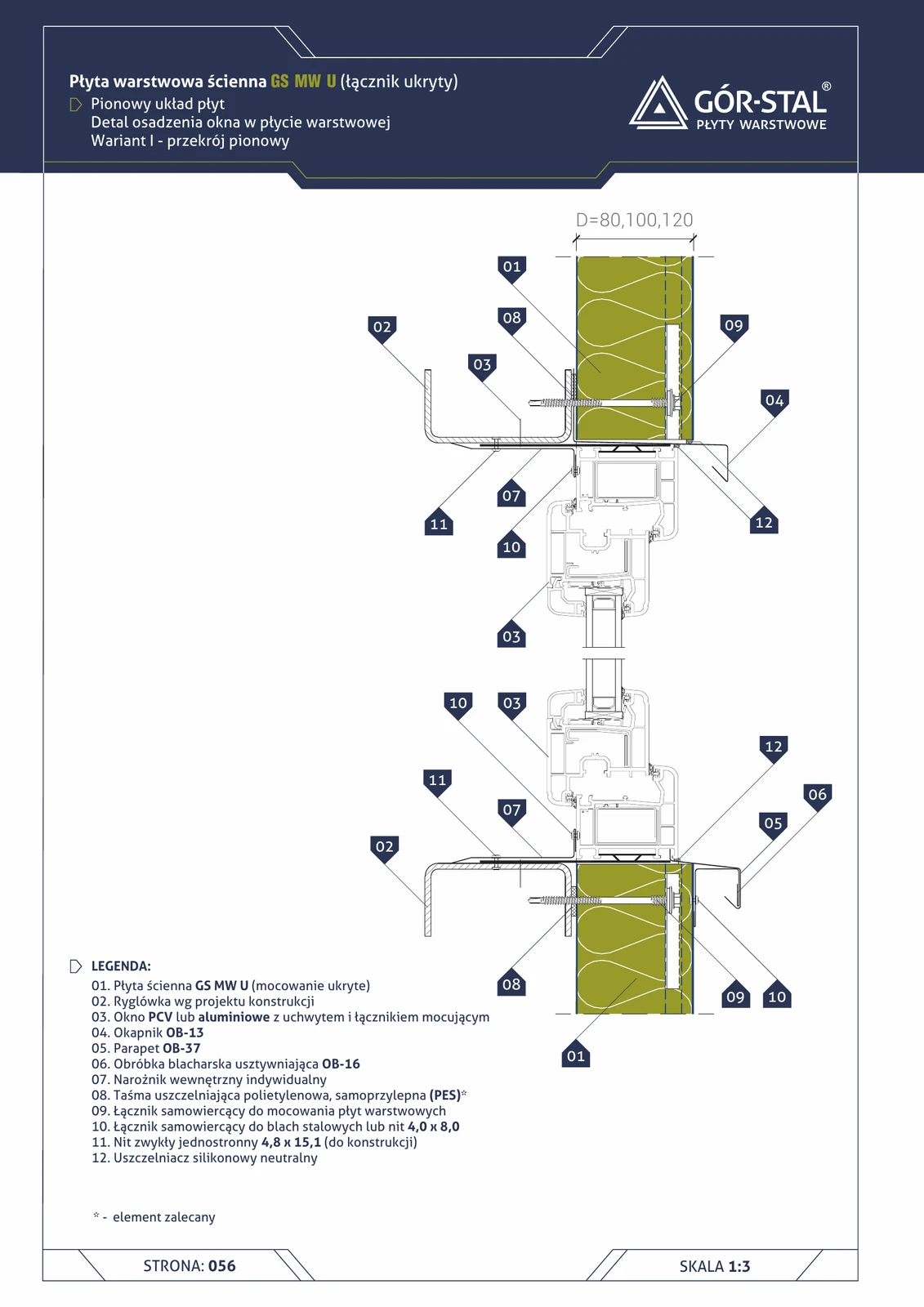
Industrial window — vertical GS MW U panel layout (vertical section)
Vertical window detail in a hall with premium vertical panels. Identical flashing composition as in S/CH (p. 27): OB-13 above window, OB-37 sill, OB-16 stiffener. Concealed panel fastening.
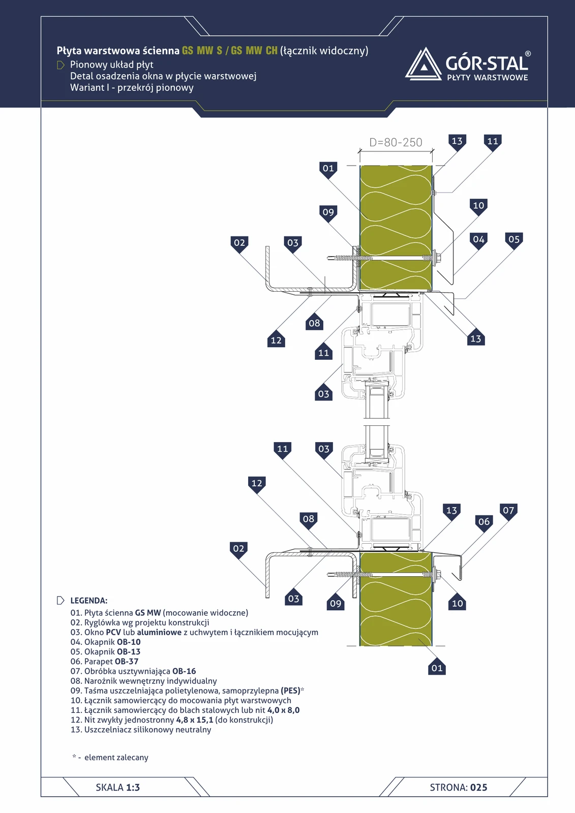
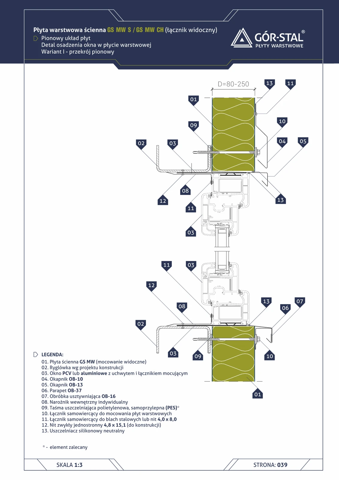
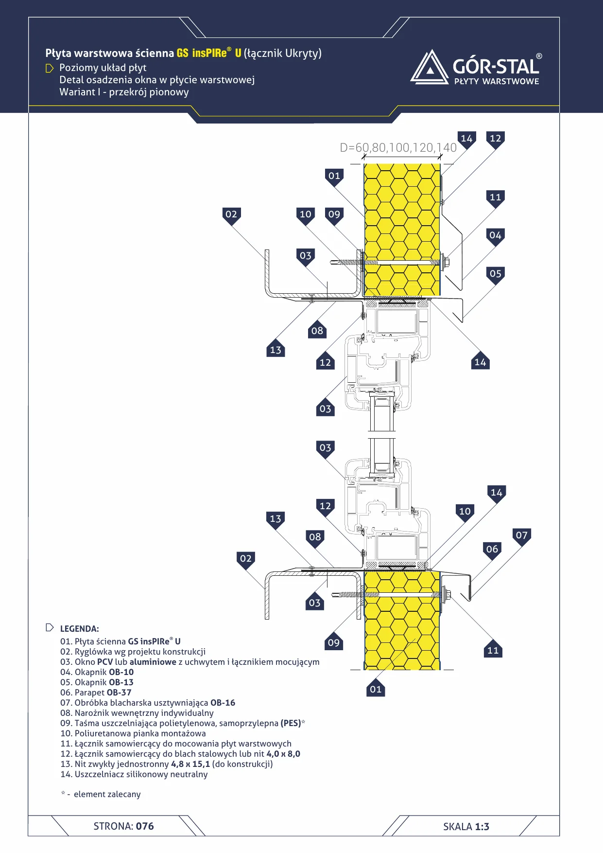
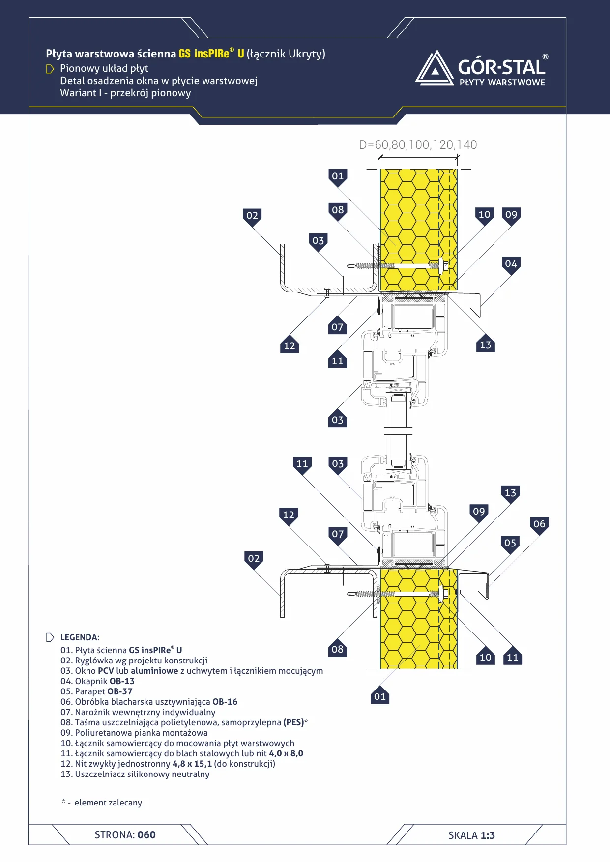
Industrial window — vertical GS MW S/CH panel layout (vertical section)
Vertical window detail in a hall with vertical sandwich panels. Complete set of 4 flashings: drip flashing above window OB-10/OB-13, window sill OB-37, stiffener OB-16 at internal sill. PVC or aluminium window with fasteners securing it to the rail framing.
Window — insPIRe® S sandwich panel (horizontal layout)
Window installation in a wall with insPIRe® S panels in horizontal layout. Variant I — panels continue above and below the window, interrupted only at the height of the opening. Different flashing geometries than the vertical layout.
Window — insPIRe® U sandwich panel (horizontal layout, concealed fastening)
Window installation in a wall of insPIRe® U panels in horizontal layout. Variant I — panels continued above and below the window. Concealed U joint + minimal visible fasteners = premium facade.
Window — horizontal insPIRe® S panel layout, variant I, horizontal section
Side window reveal in horizontal PIR panel layout. Custom cover flashings + internal corner trims finish the frame sides. Same principles as vertical layout (p. 27).
Window — horizontal insPIRe® S panel layout, variant II, horizontal section
Side jamb in simplified variant with mounting profile. Window profile directly against the panel.
Window — horizontal insPIRe® S panel layout, variant II, vertical section
Simplified window installation with mounting profile in horizontal PIR layout. Window profile directly on the panel, without additional side flashings. OB-11 drip edge optional.
Window — vertical insPIRe® S panel layout, variant I, horizontal section
Side reveal of a window in a vertical PIR panel layout (horizontal section = top view). Custom trim flashings + custom internal corners finish the sides of the window frame. Fixed with blind rivets.
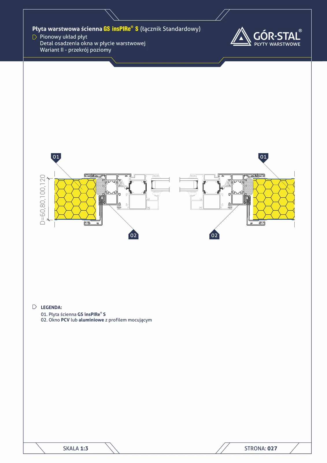
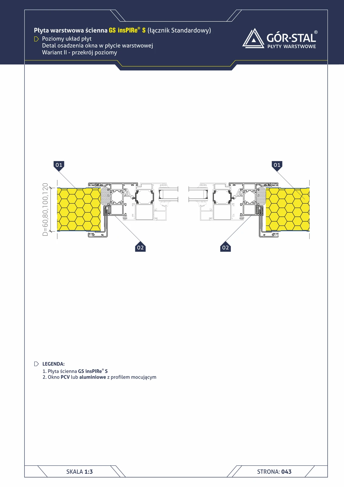
Window — vertical insPIRe® S panel layout, variant II, horizontal section
Side jamb in a simplified variant with mounting profile. The window profile sits directly against the panel edge — no additional side flashings.
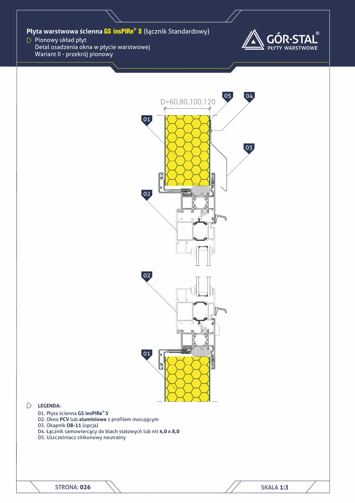
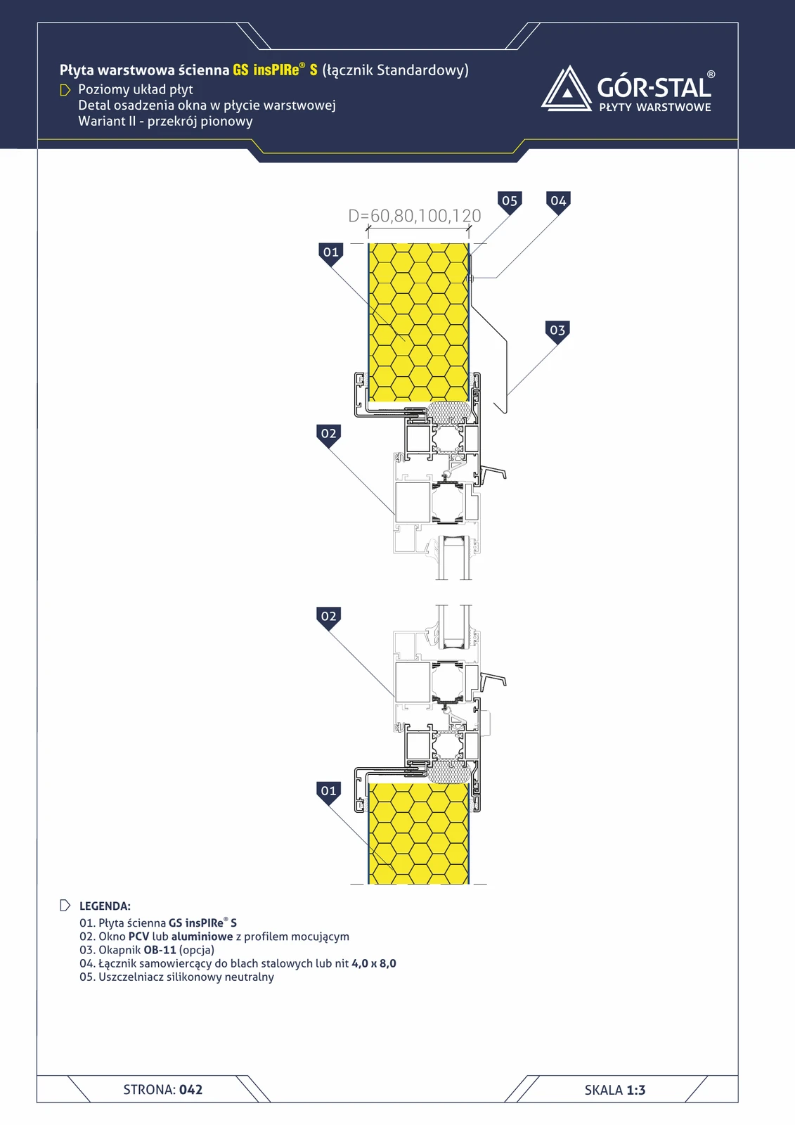
Window — vertical insPIRe® S panel layout, variant II, vertical section
Simplified window installation with mounting profile — no additional jamb flashings. Window profile directly adjacent to the panel edge. OB-11 drip flashing optional.
Window — horizontal insPIRe® U panel layout, variant I, horizontal section
Side window jamb in premium horizontal PIR layout. Custom cover flashings + internal corners + PM1 backing plates in panels around the window.
Window — horizontal insPIRe® U panel layout, variant II, horizontal section
Side jamb of variant II with mounting profile.
Window — horizontal insPIRe® U panel layout, variant II, vertical section
Simplified window installation with mounting profile in premium horizontal PIR layout. OB-11 drip flashing optional + additional flashing at panel joint.
Window — vertical insPIRe® U panel layout, variant I, horizontal section
Side window jamb in premium vertical PIR layout. Custom cover flashings + internal corner profiles.
Window — vertical insPIRe® U panel layout, variant II, horizontal section
Side jamb in simplified U variant with mounting profile.
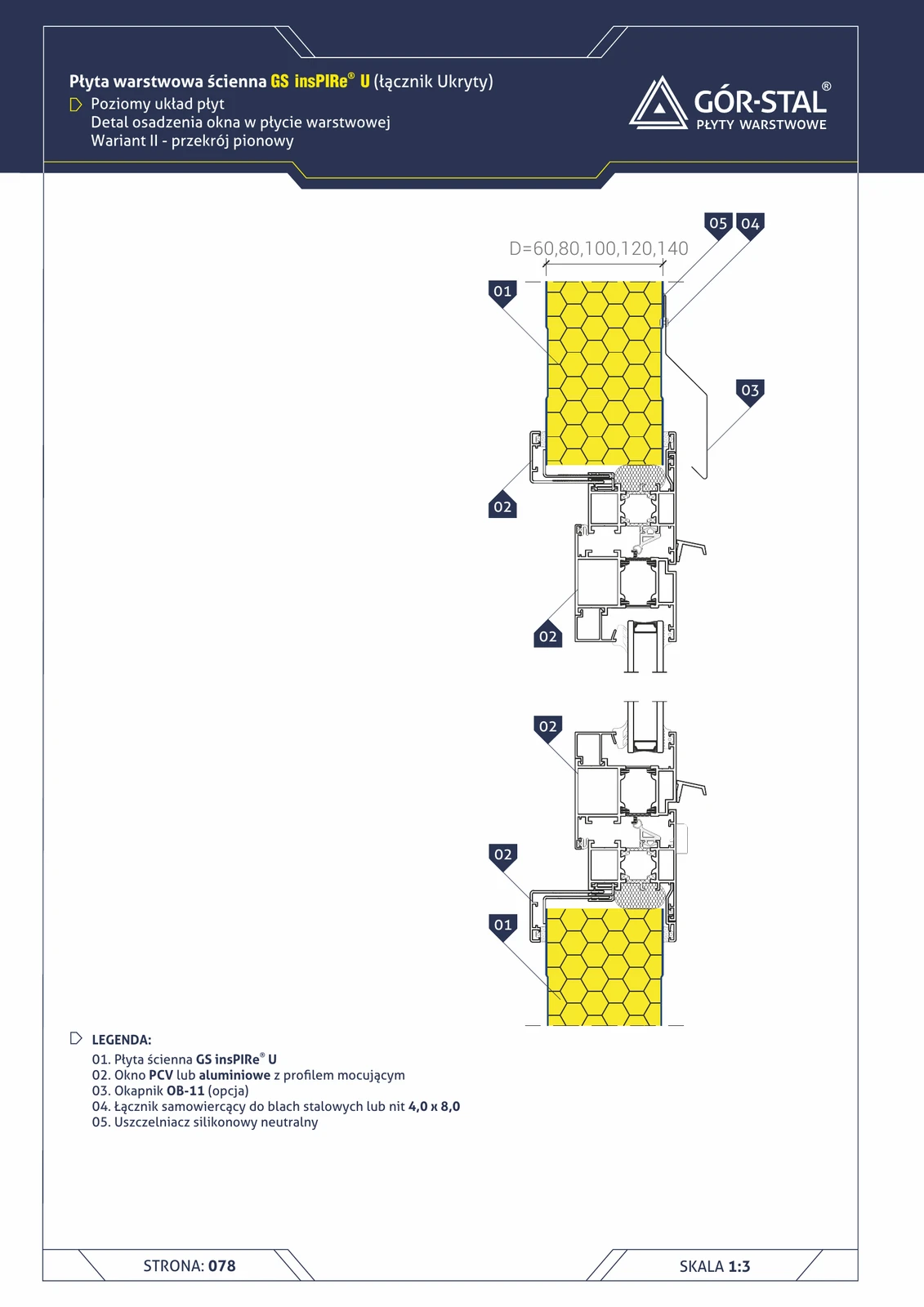
Window — vertical insPIRe® U panel layout, variant II, vertical section
Simplified window installation with mounting profile in premium vertical PIR layout. Optional OB-11 drip flashing + additional flashing at panel joint.
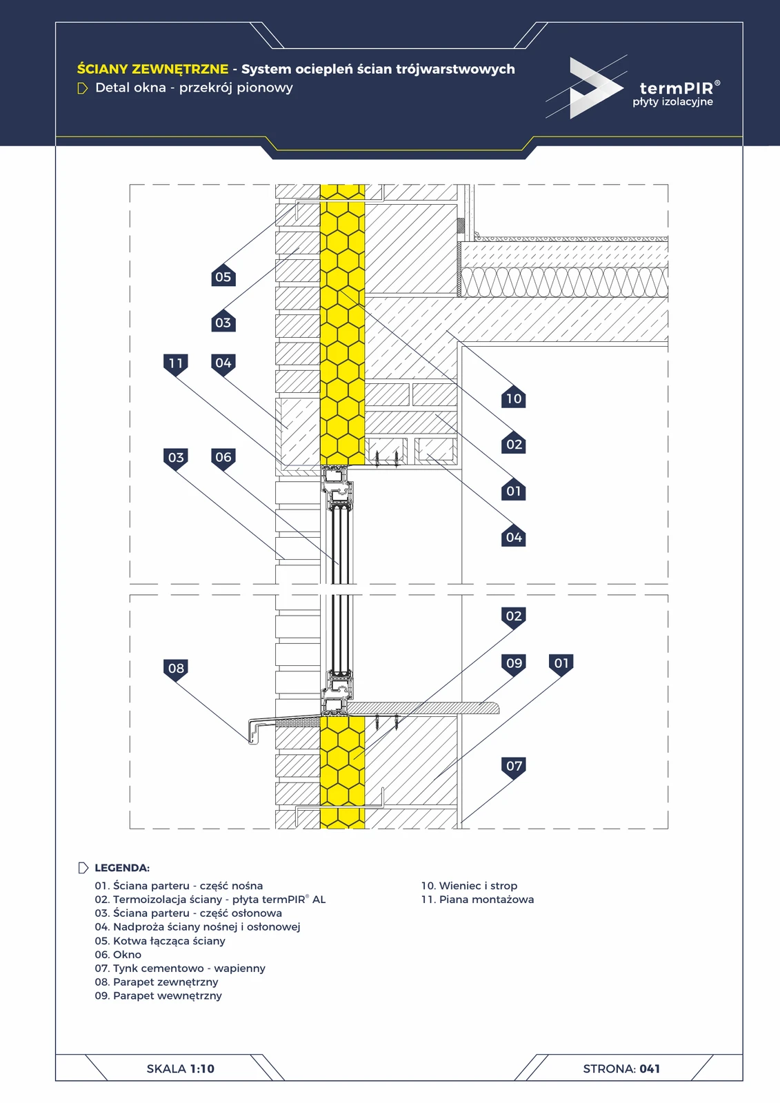
Window in three-layer wall — vertical section
Vertical window installation in a three-layer wall. Requires **two lintels** — one in the load-bearing layer, one in the facing layer. termPIR® AL continuous around the frame, low-expansion foam in the gap. External sill with drip edge.
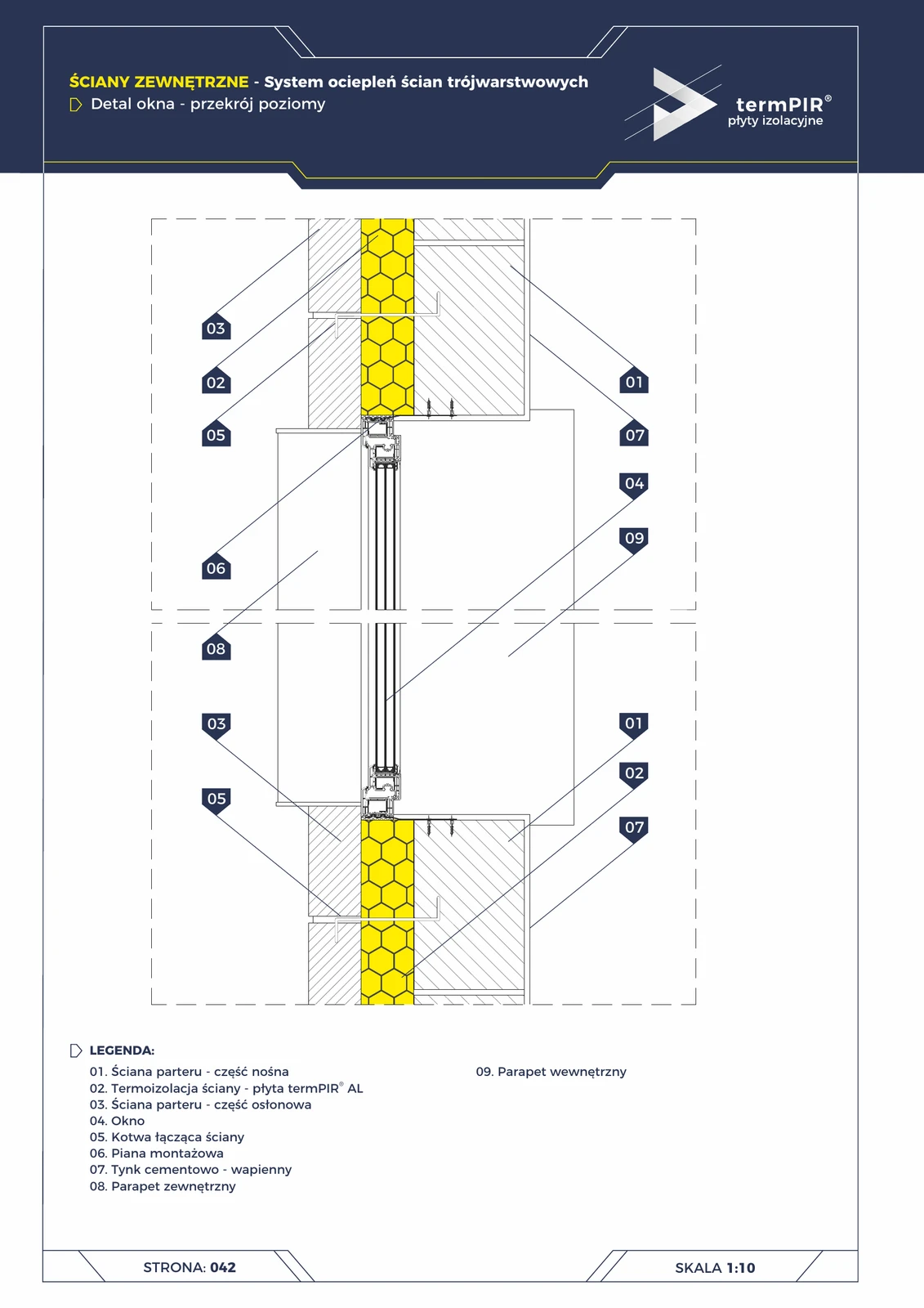
Window in three-leaf wall — horizontal section
Horizontal detail of window installation in a three-leaf wall. Side reveals require continuation of the termPIR® AL layer between the load-bearing and outer leaf — without this, a linear thermal bridge is visible in thermography. Stainless steel anchors tie both walls together.
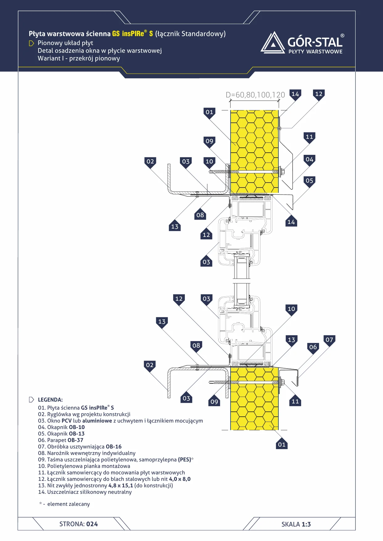
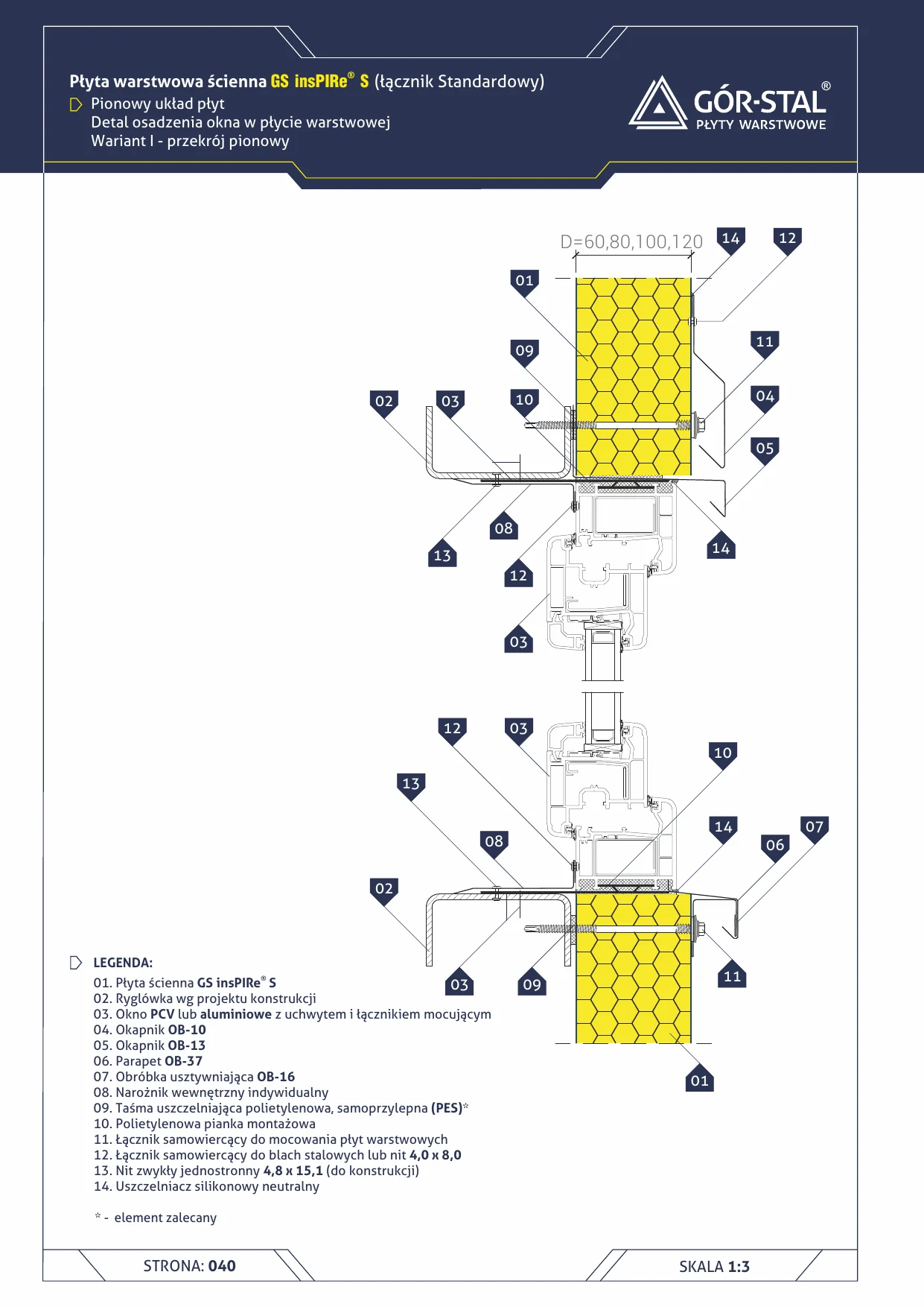
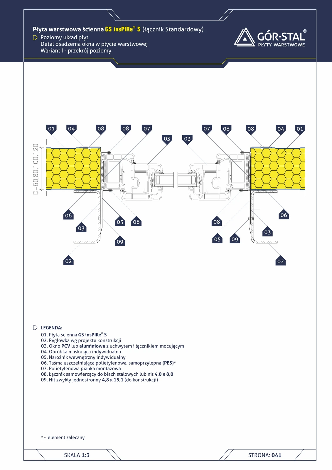
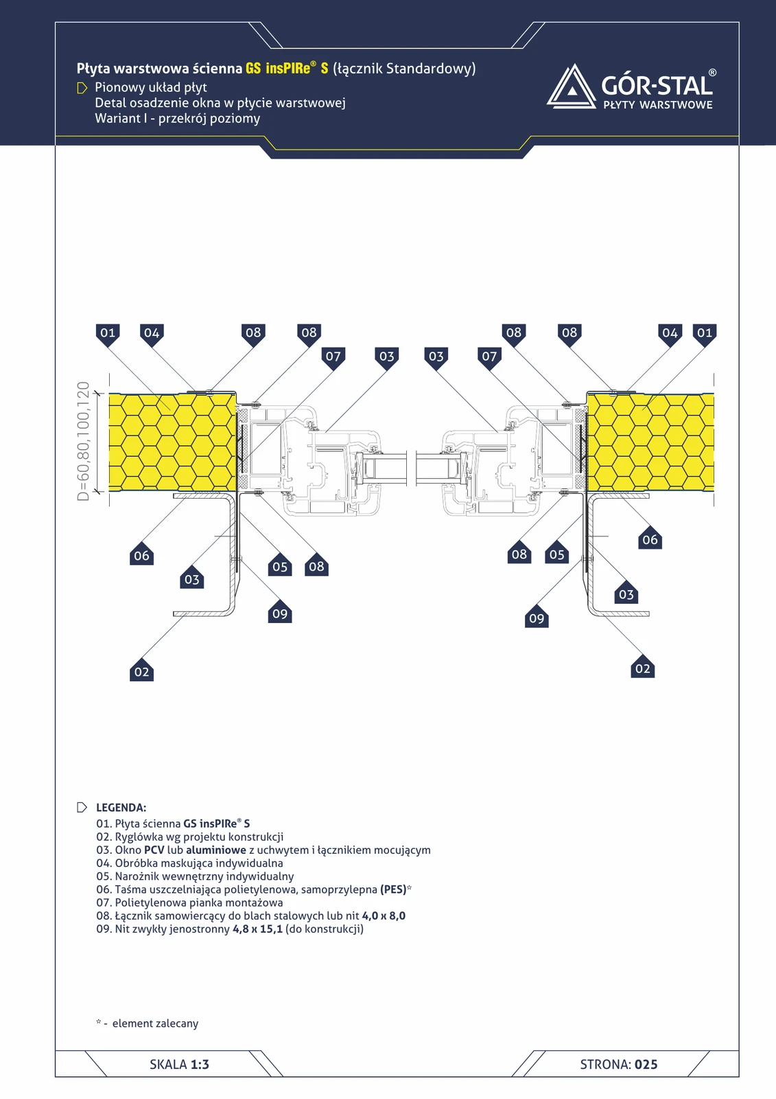
Window — insPIRe® S sandwich panel (vertical layout)
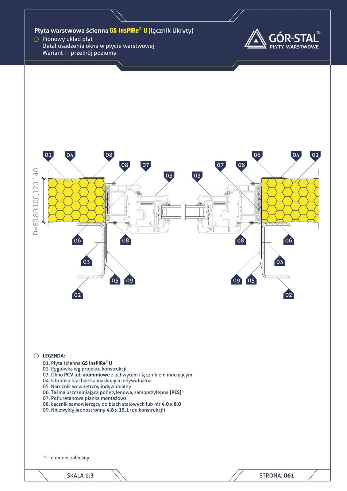
Window installation in an industrial hall wall with insPIRe® S panels in vertical layout. Variant I with OB-01/OB-02 corner flashings, steel frame and PES + PU foam sealing.
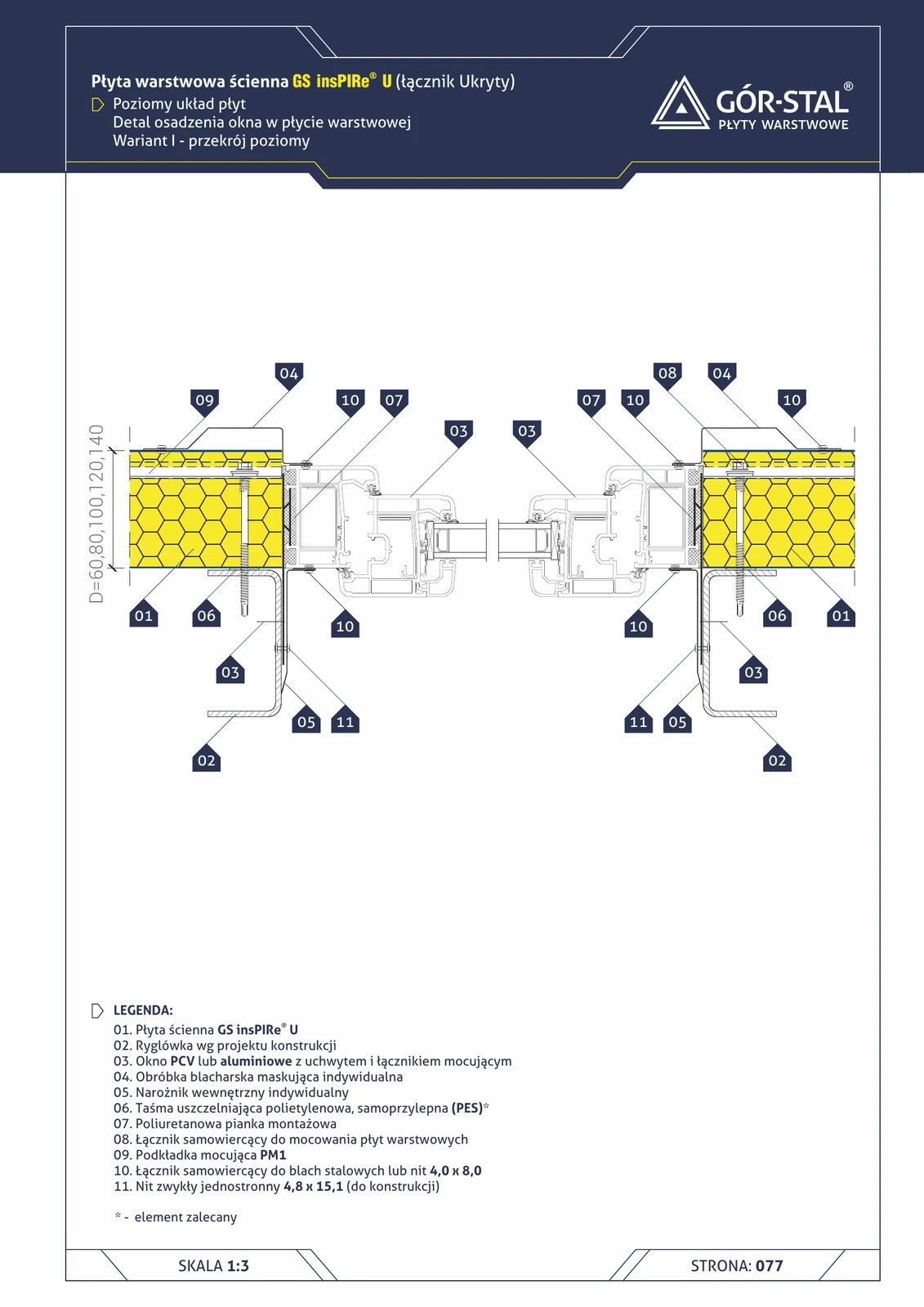
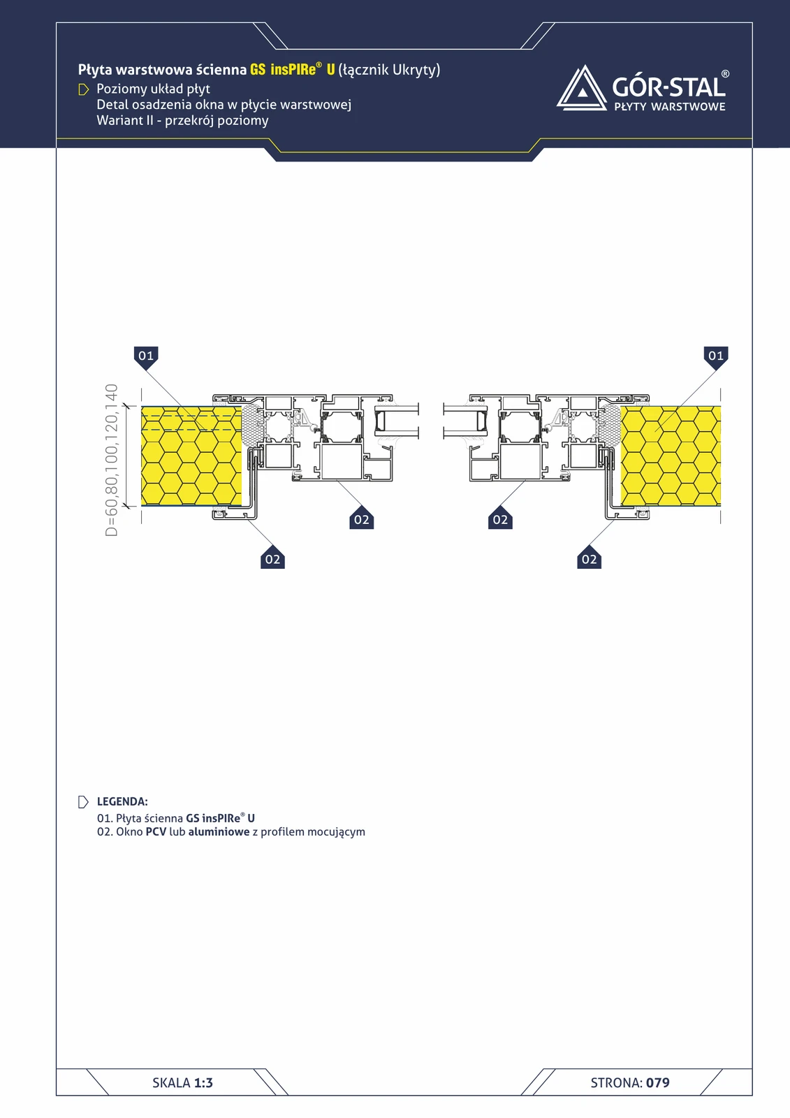
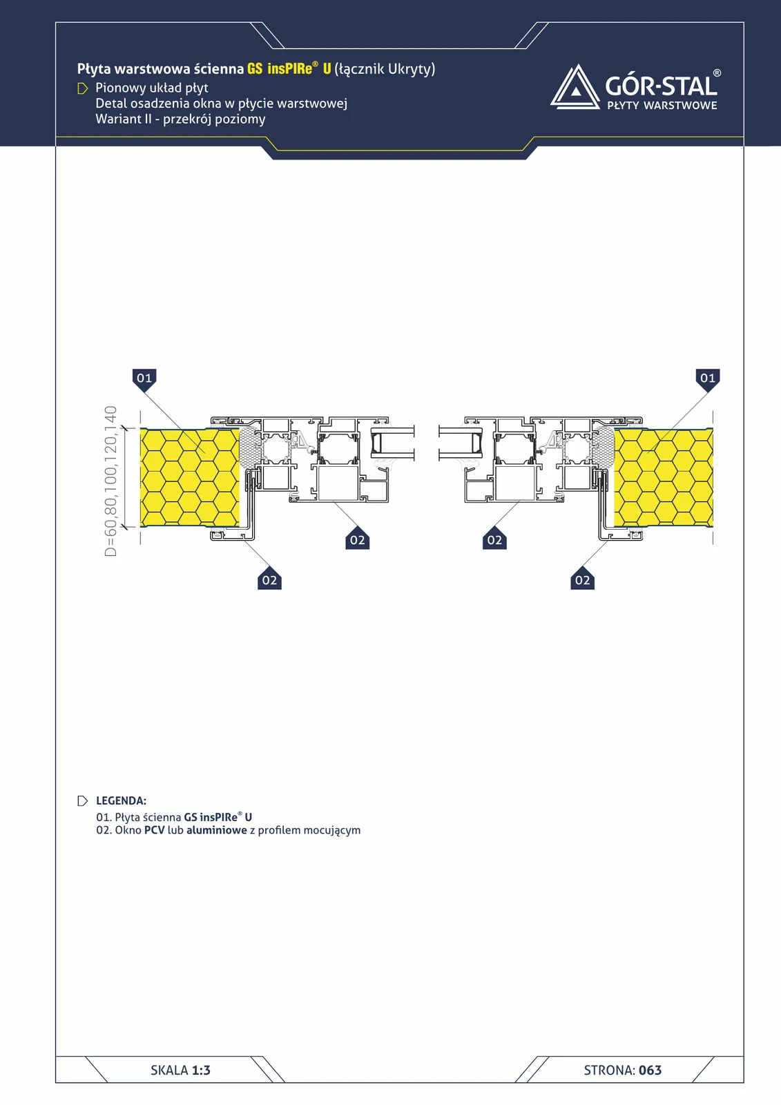
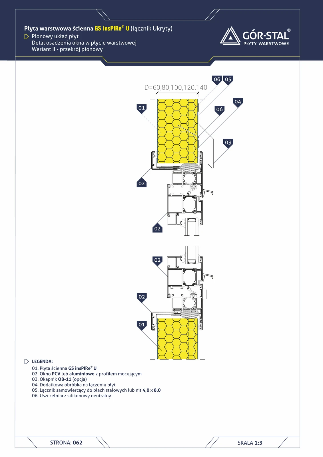
Window — insPIRe® U sandwich panel (vertical layout, concealed fixing)
Window installation in a hall with insPIRe® U panels in vertical layout, Variant I. The U panel has a concealed joint — fasteners are invisible from outside, providing a smooth façade line around the opening.
Gate opening (17)
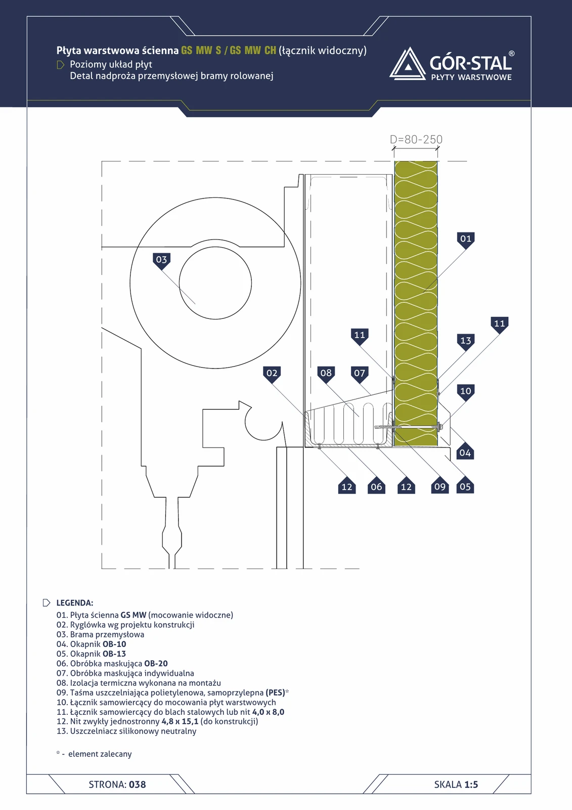
Industrial door lintel — horizontal GS MW S/CH panel layout
Top edge of the door opening in a hall with horizontal sandwich panel layout. Requires OB-10 / OB-13 drip flashing for rainwater drainage + OB-20 trim flashing + custom flashing matching the door guide rails.
Industrial door lintel — horizontal GS MW U panel layout
Top edge of the door opening in premium horizontal GS MW U panels. OB-10 drip flashing drains water; dual custom flashings conceal the joint with the door + sub-framing.

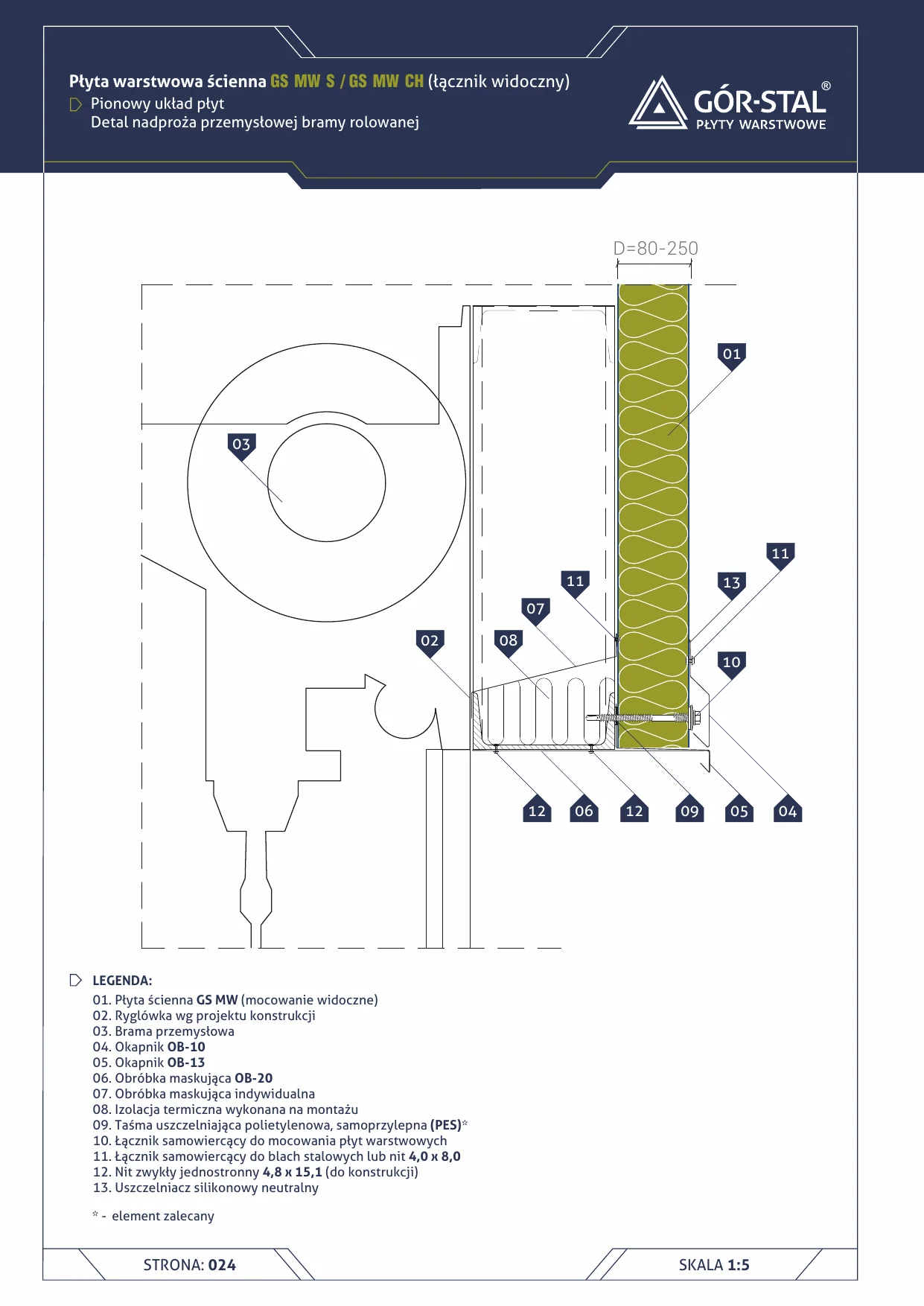
Industrial door lintel — vertical GS MW S/CH panel layout
Top edge of door opening in vertical GS MW S (visible fixing) or CH (cold storage) panels. OB-10 drip flashing above door, OB-13 above panel face, OB-20 cover trim conceals the joint. Custom flashings tailored to door type.
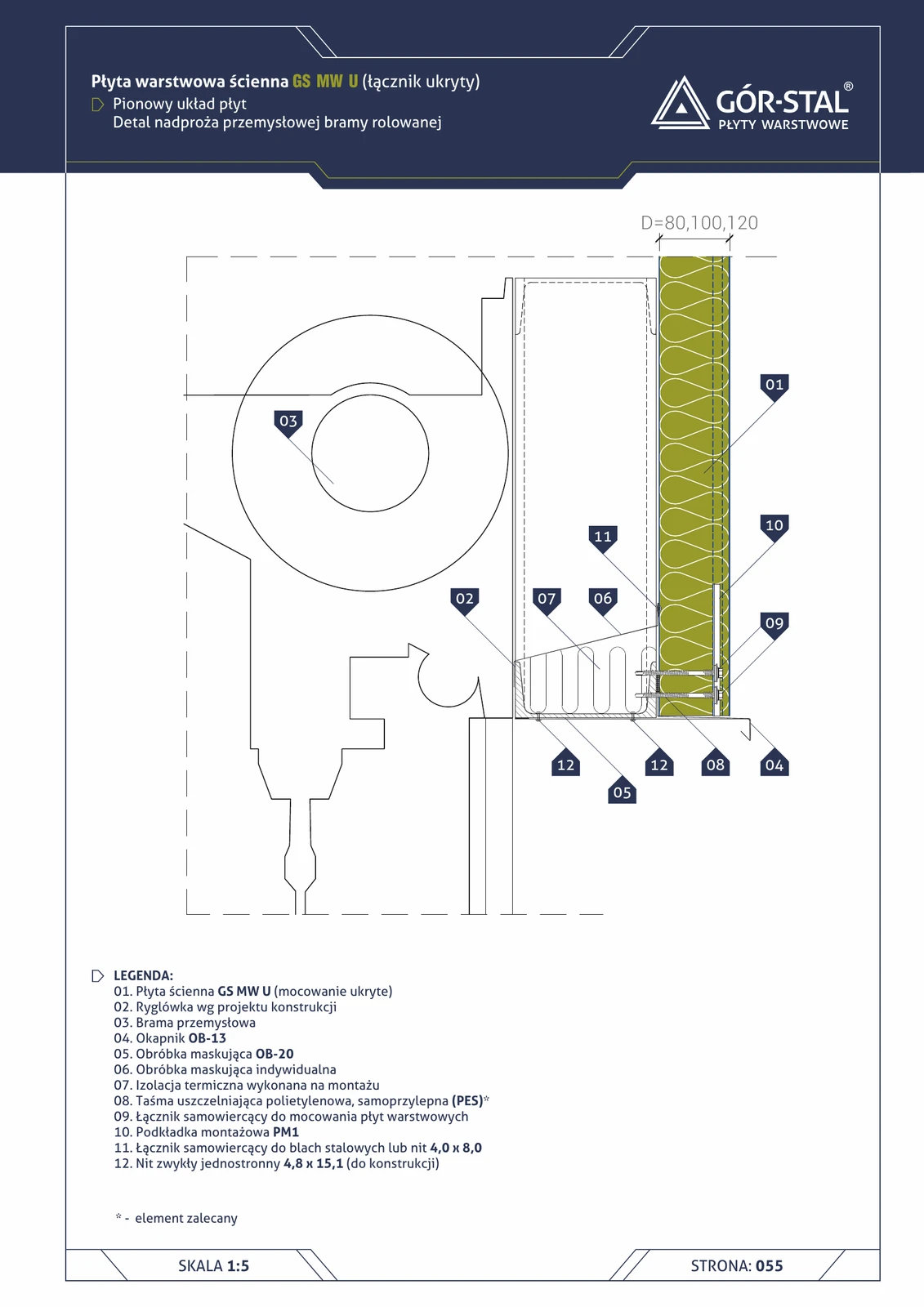
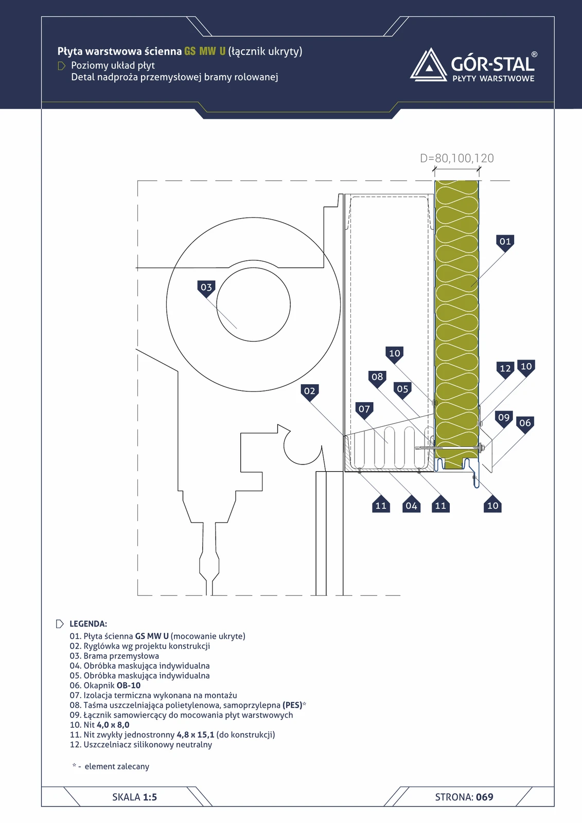
Industrial door lintel — vertical GS MW U panel layout
Top edge of door opening with vertical GS MW U panels. OB-13 drip flashing drains water, OB-20 cover flashing conceals the joint, custom flashings fitted to the door. Premium aesthetics with concealed fasteners in panels.
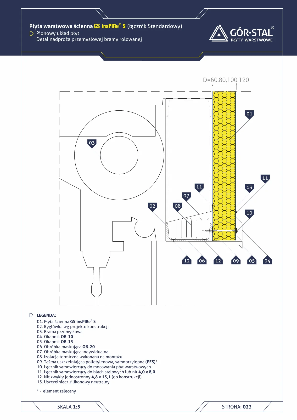
Door lintel — vertical sandwich panel S layout
Industrial roller door lintel seated in an insPIRe® S sandwich panel wall in vertical layout. Standard solution for warehouses and retail buildings.
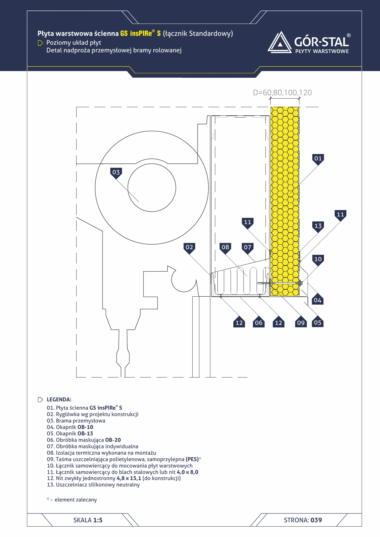
Gate lintel — horizontal sandwich panel S layout
Industrial gate lintel seating in a wall built from insPIRe® S panels in horizontal layout. Panels continue on both sides of the gate — more economical for retail buildings.
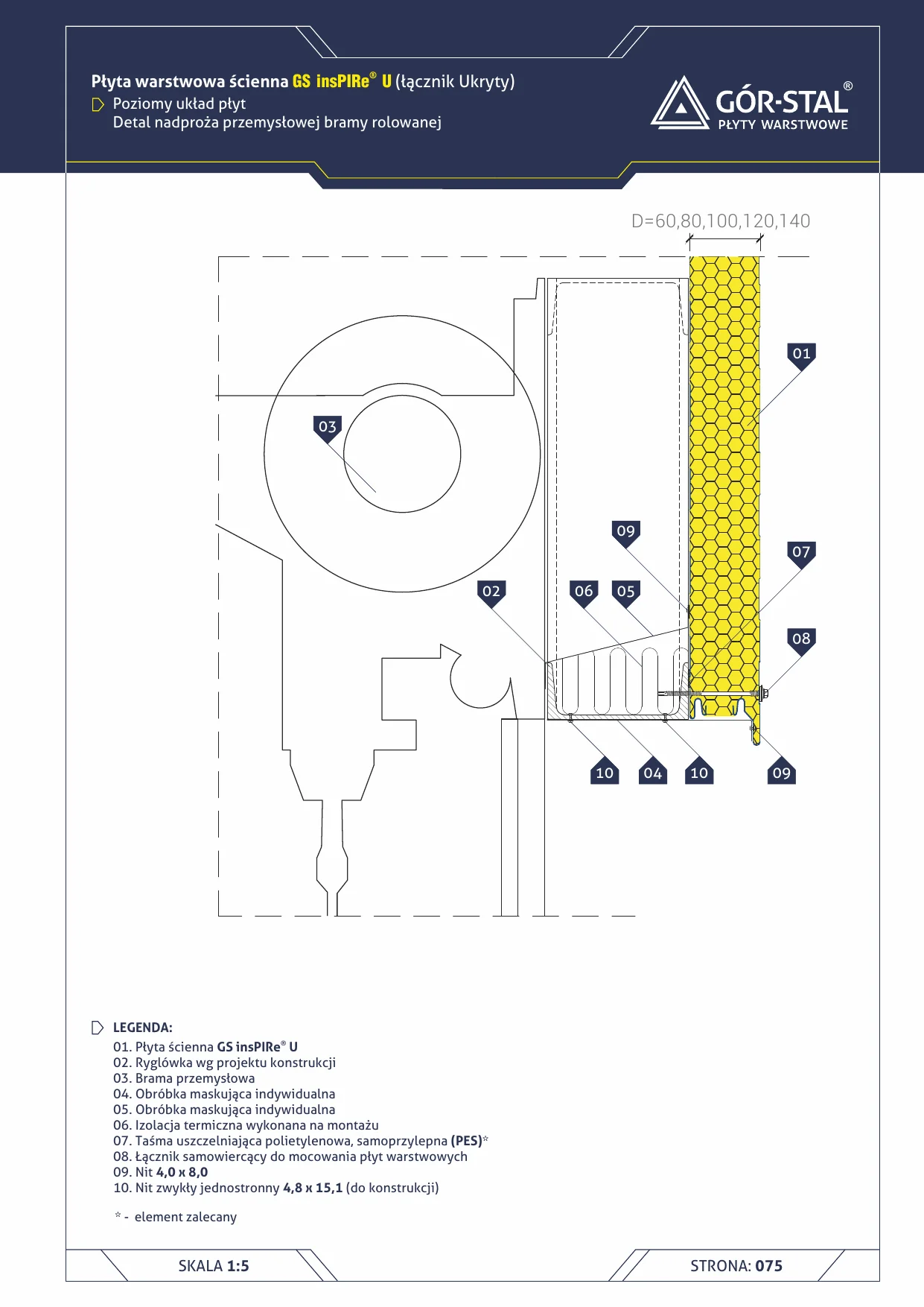
Gate lintel — horizontal U sandwich panel layout (concealed fixing)
Gate lintel set into a wall of insPIRe® U panels laid horizontally. Panels continue at the sides of the gate + concealed joint = the most minimalist geometry around a gate in our portfolio.
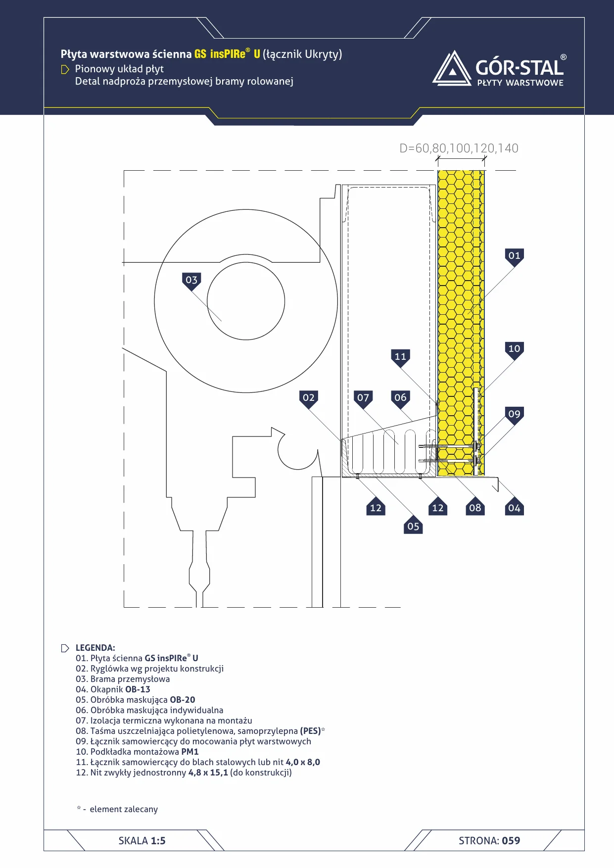
Gate Lintel — Vertical Layout with U Sandwich Panels (Concealed Fixing)
Industrial roller gate lintel installation in a wall of insPIRe® U panels in vertical layout. Panel fasteners concealed in the joint — only OB-20/OB-21 flashing fasteners are visible.
Industrial Gate Post — Horizontal GS MW U Panel Layout
Side jamb of an industrial gate in a hall with horizontal premium GS MW U panels. Custom gate flashing (instead of the typical OB-21 used with S/CH — the U-lock geometry requires adaptation) + PM1 concealed fixing.
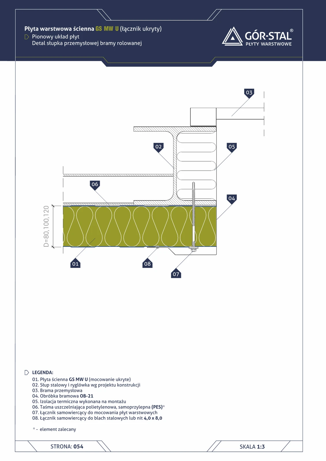
Industrial gate post — vertical GS MW U panel layout
Side jamb of a roller gate in a hall with vertical premium GS MW U panels. OB-21 gate flashing conceals and seals the joint; mineral wool fills the installation cavity. Functionally identical to S/CH (p. 25), the difference = concealed panel fastening.
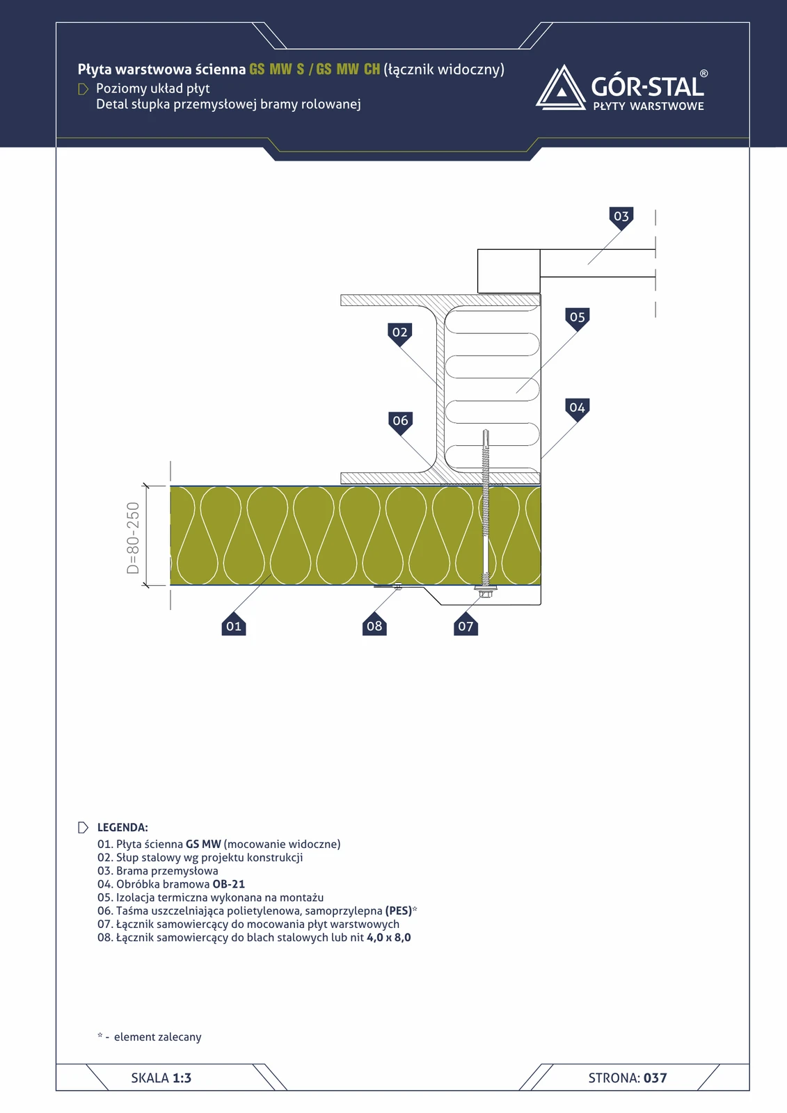
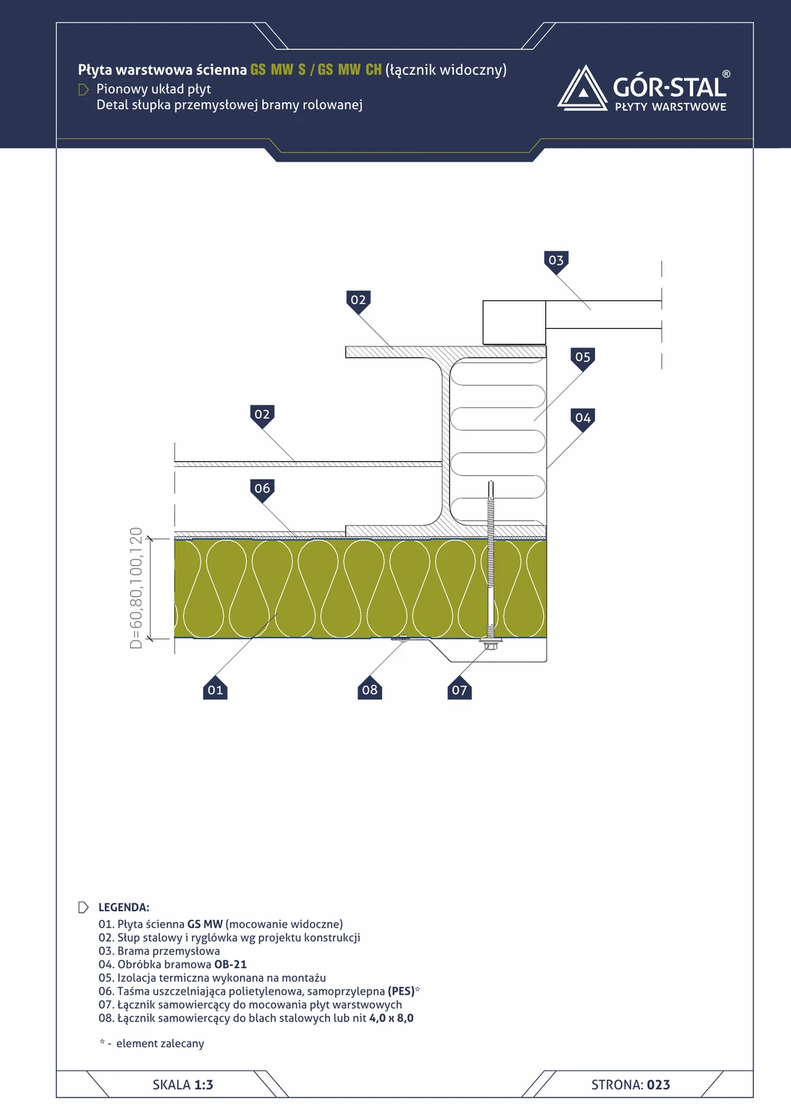
Industrial gate post — horizontal GS MW S/CH panel layout
Side jamb of an industrial gate in a hall with horizontal panel layout — analogous to the vertical layout (p. 25), differing only in panel orientation. OB-21 gate flashing covers and seals the junction, mineral wool fills the installation gap.
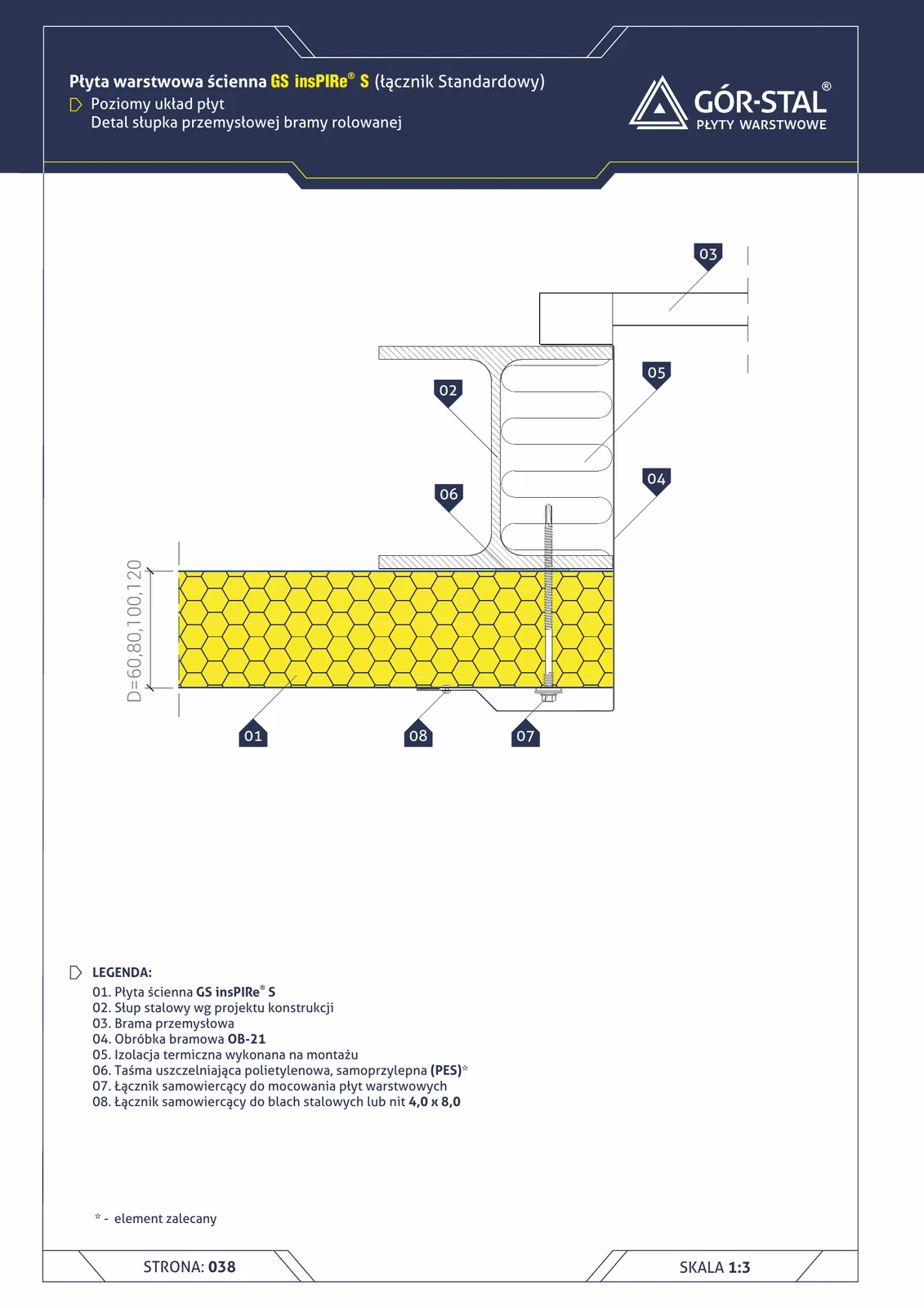
Industrial gate post — horizontal insPIRe® S panel layout
Side gate jamb in a hall with horizontal PIR panel layout. OB-21 gate flashing, thermal insulation within the installation space. Functionally analogous to the vertical layout (p. 24).
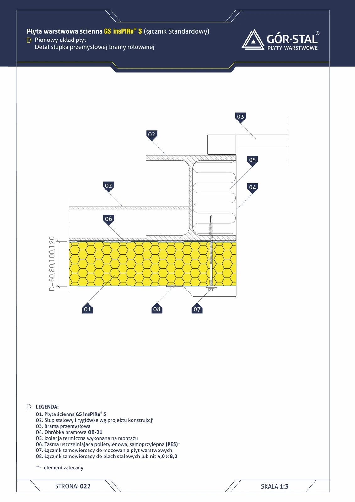
Industrial gate post — vertical insPIRe® S panel layout
Side jamb of an industrial roller gate in a hall with vertical PIR panels. OB-21 gate flashing conceals and seals the panel-to-jamb joint. Reinforced for forklift traffic.
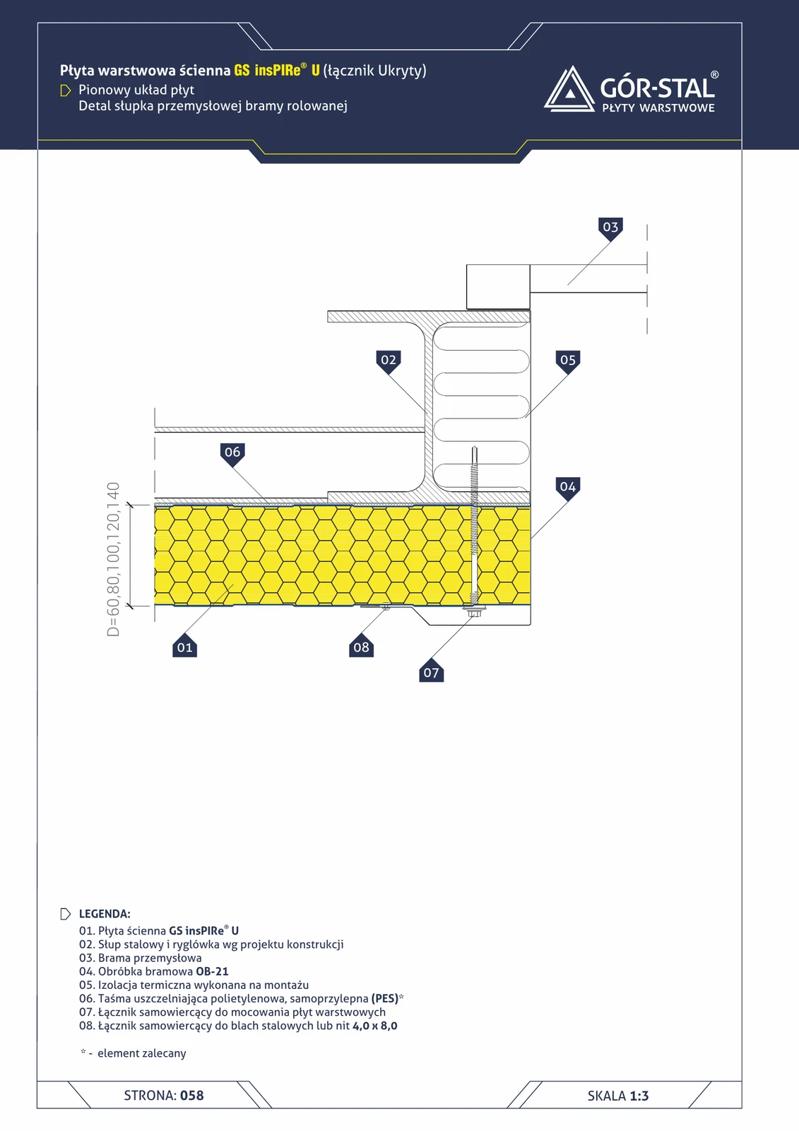
Industrial gate post — horizontal insPIRe® U panel layout
Side gate jamb in a hall with premium horizontal PIR panels. Custom gate flashing (instead of OB-21 with S) + PM1 concealed fastening.
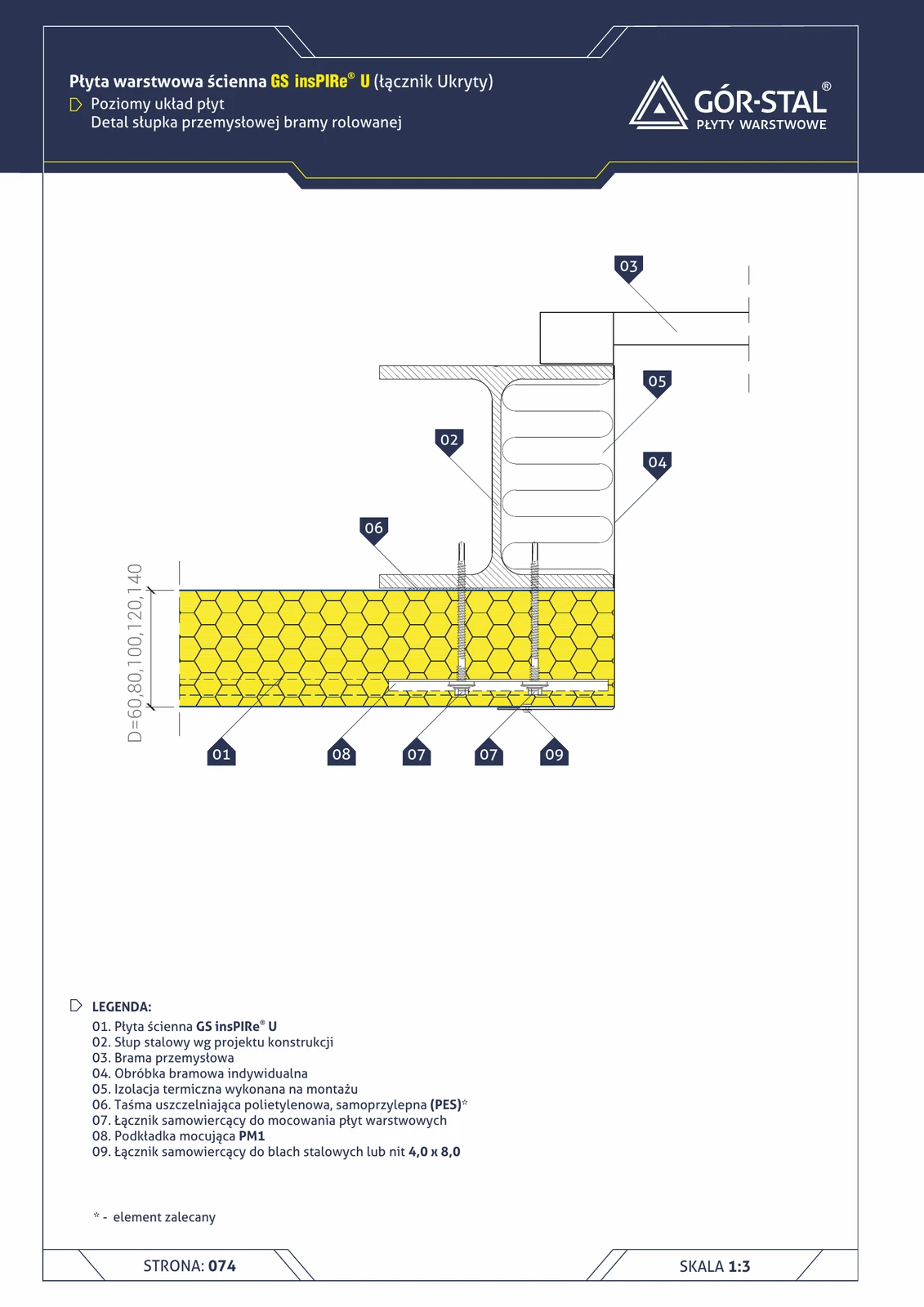
Industrial gate post — vertical insPIRe® U panel layout
Side gate jamb in a hall with premium vertical PIR panels. OB-21 gate flashing, insulation in the installation space.
Industrial door jamb — vertical GS MW S/CH panel layout
Side jamb of a rolling industrial door (typical width 3-5 m, height 3-4 m) in a hall with vertical sandwich panels. OB-21 door flashing conceals and seals the joint between the panel and the door frame; thermal insulation installed on site.
Roller door lintel — GS MW (non-combustible A2)
Industrial roller door lintel set in a wall built from GS MW S or CH mineral wool panels. Reinforced steel structure above the opening required, class A2-s1,d0.
Door opening (4)
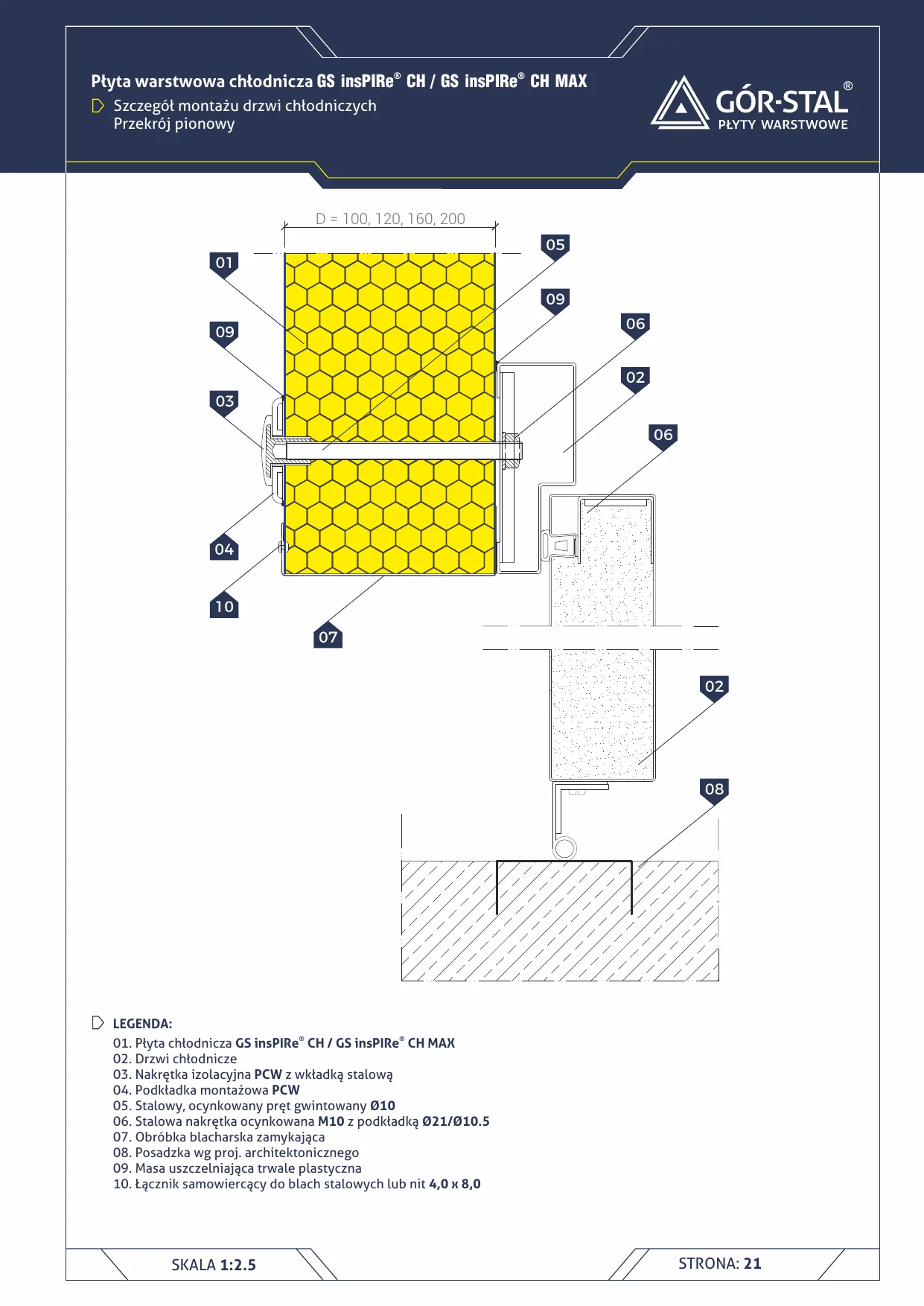
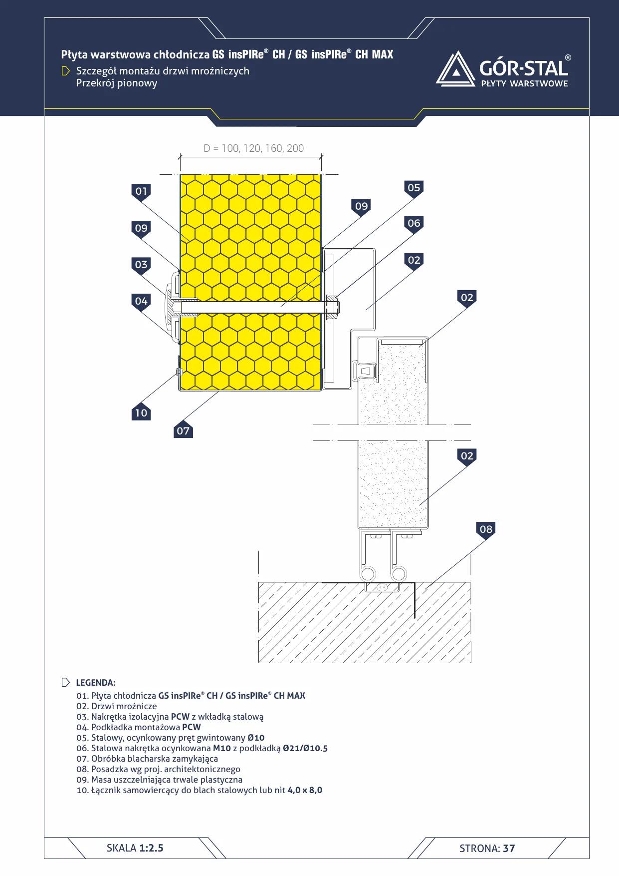
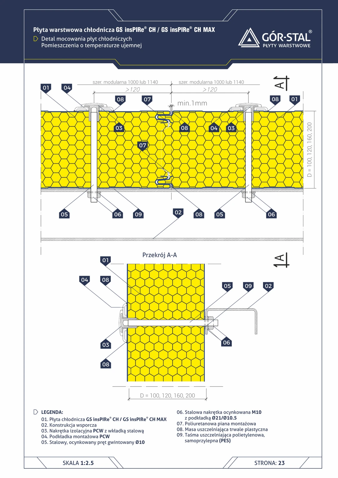
Cold room door — vertical section
Cold room door installation in GS insPIRe® CH panel wall — lintel and threshold in a single section. PVC rod-nut system ensures thermal tightness at t > 0°C.
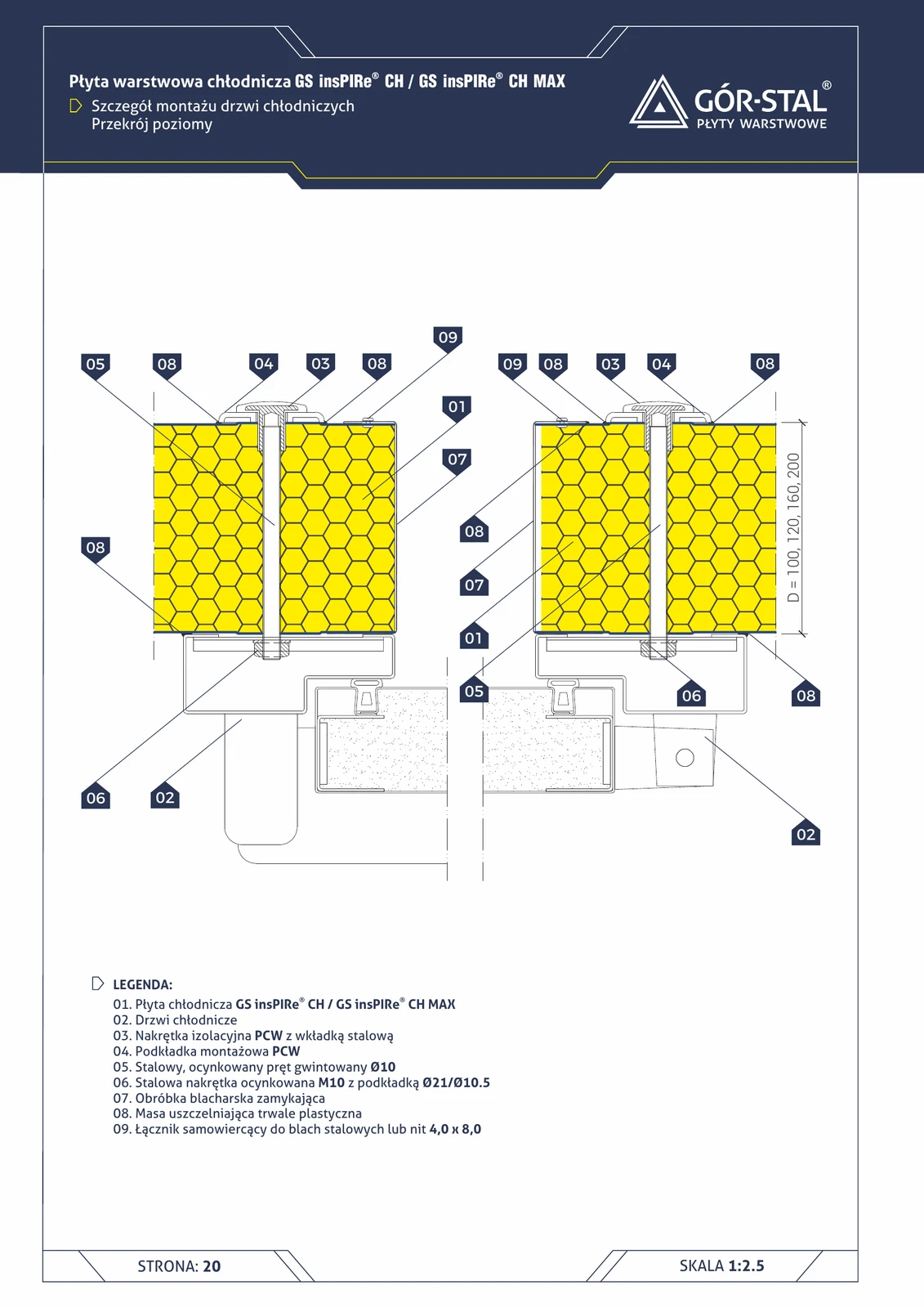
Cold storage door — horizontal section (side jambs)
Cold storage door side jambs fixed on a **Ø10 threaded rod** passing through the panel. **PVC insulating nuts** prevent thermal bridges through steel fasteners. Standard for all cold rooms.
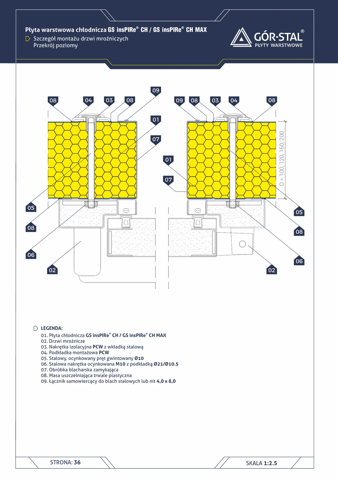
Freezer door — horizontal section (side jambs)
Freezer door side jambs fixed on a **Ø10 threaded rod** with **PVC insulating nuts**. Identical solution as the cold room door (p. 22), but **with more stringent sealing** for a 50°C gradient.
Freezer Door — Vertical Section
Freezer door installation in chamber t < 0°C — requires frame and threshold heating to prevent freezing. Without heating, doors lock up after a few cycles.
Wall junction (21)
Top-storey floor + knee wall
The trickiest detail when insulating a floor below an unheated attic: the junction with the knee wall (role: maintain insulation continuity between termPIR AL on the floor + ETX on the wall + insulated wall plate). Without it, you get a linear thermal bridge ψ ≈ 0.3 W/m·K.
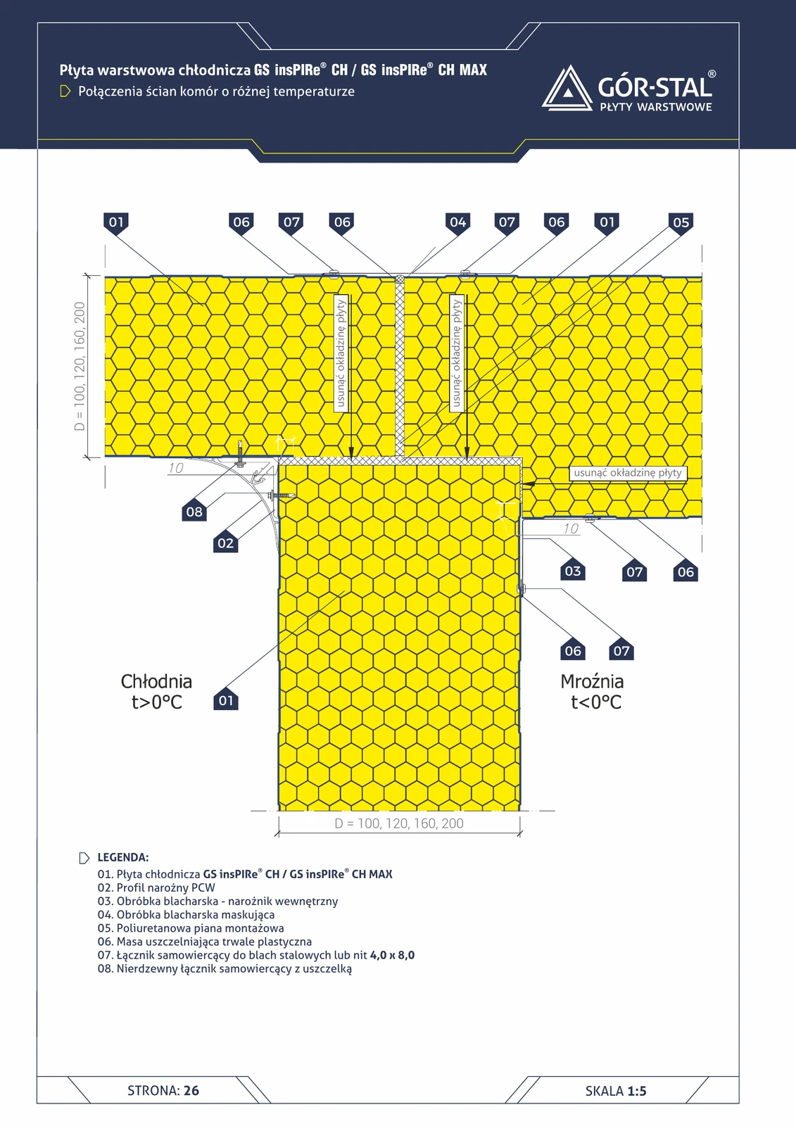
Connection of chamber walls with different temperatures (cold room + freezer)
The most challenging detail in cold-storage facilities: junction of a **cold room (t > 0°C)** with a **freezer (t < 0°C)**. Temperature gradient of 30-40°C in a single node. Facings of **both panels** removed in the joint zone, PVC corner profile + OB-02 + OB-18.
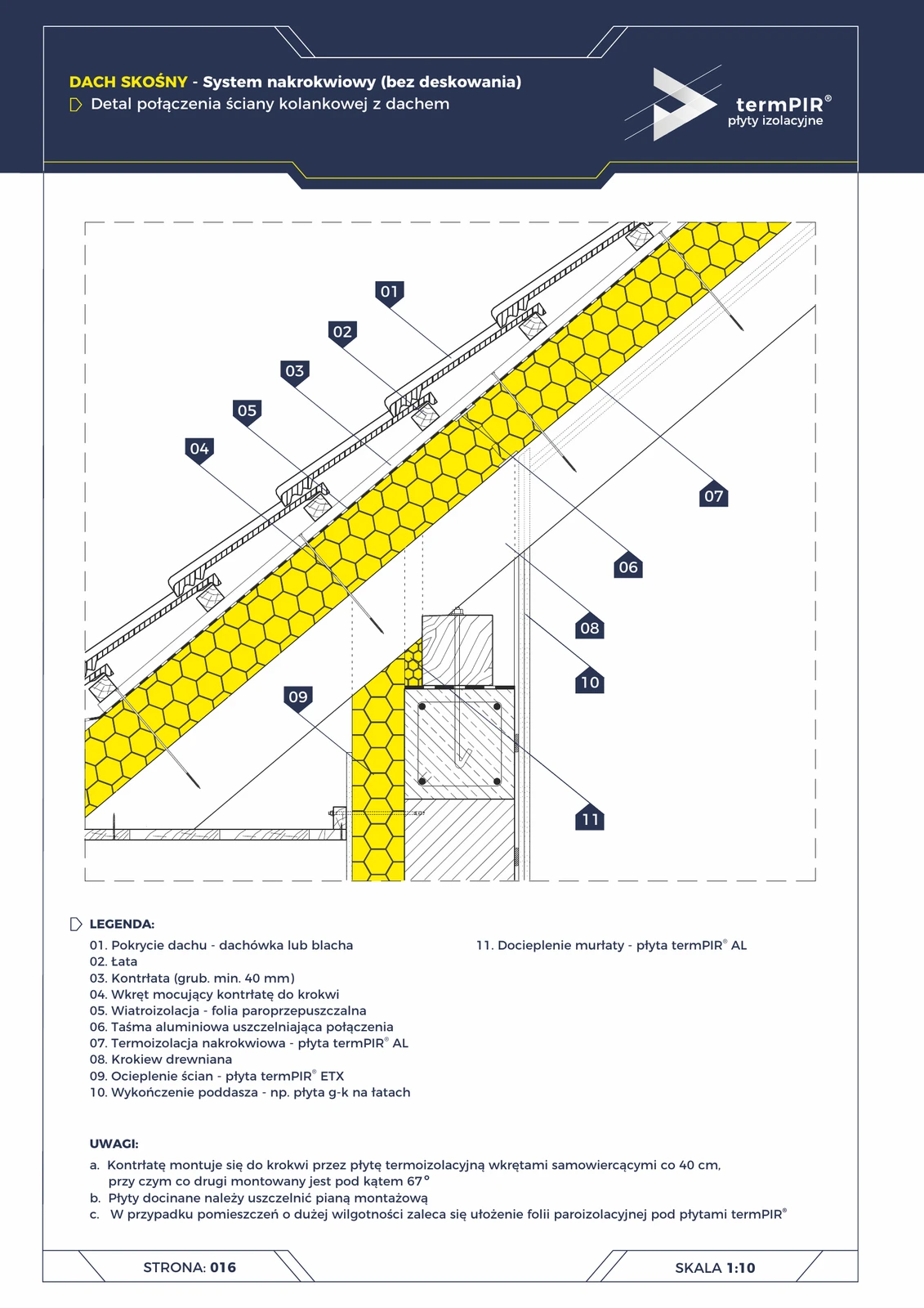
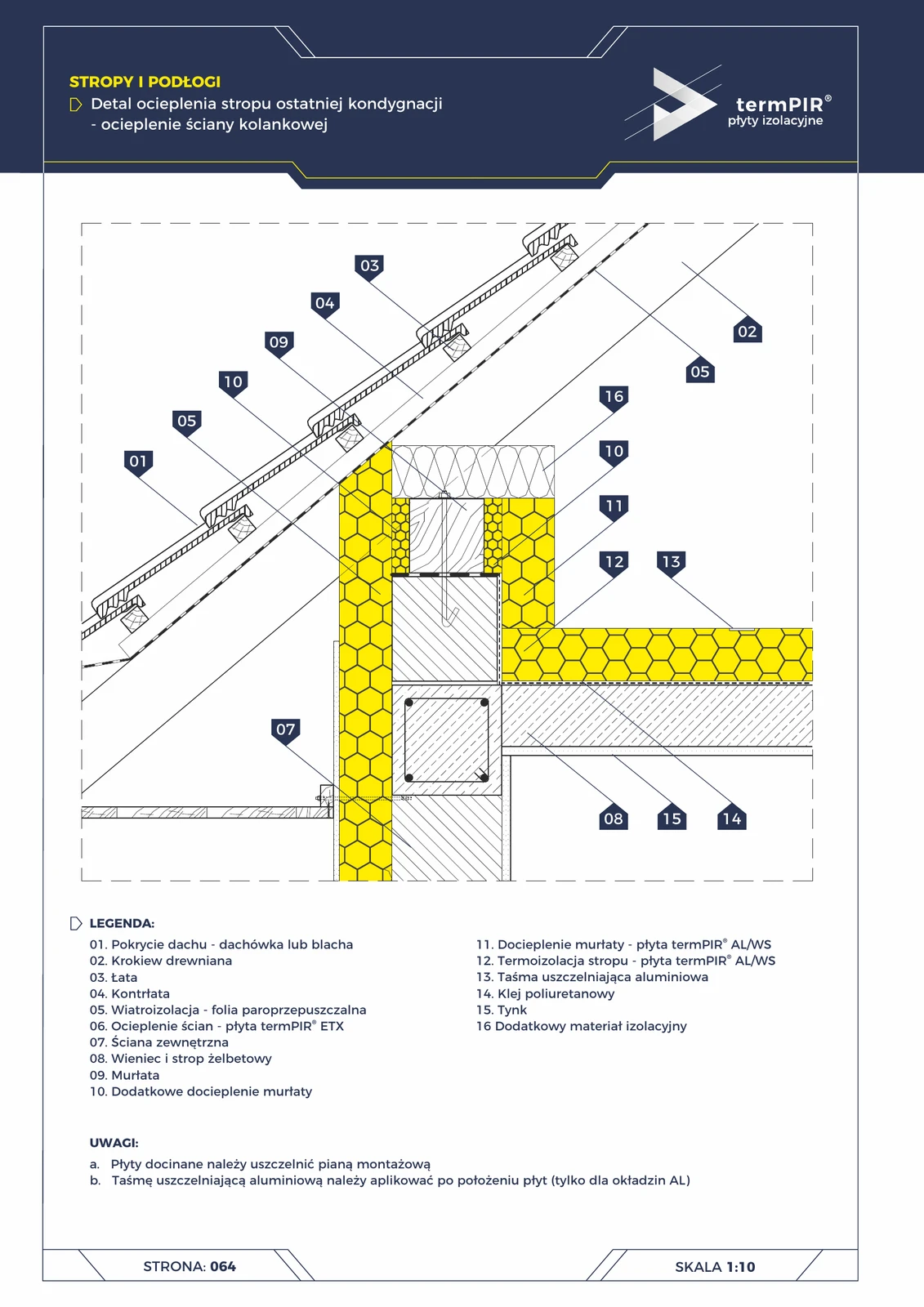
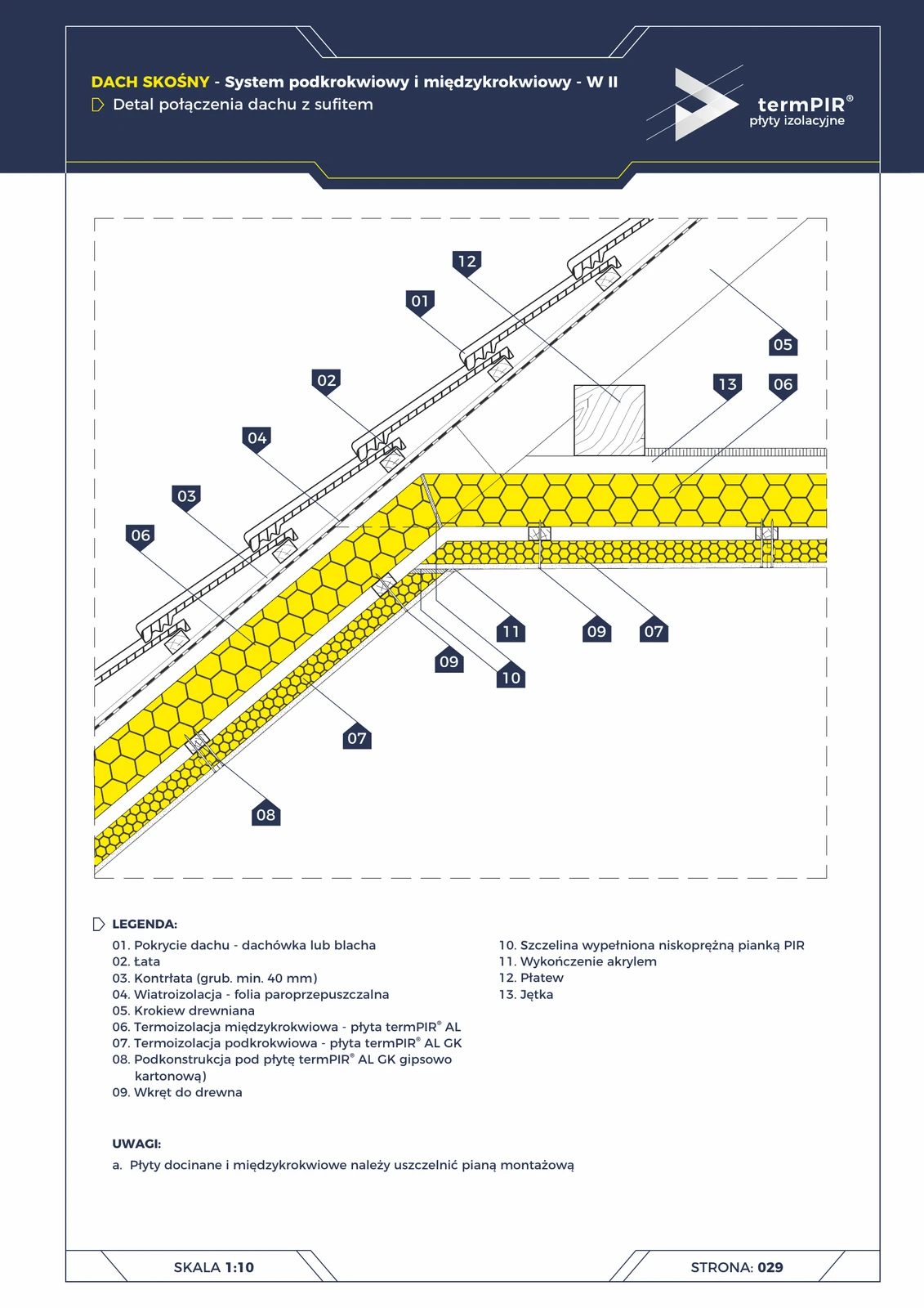
Knee wall — over-rafter roof (termPIR® AL + ETX)
The trickiest detail of a pitched roof: where over-rafter insulation meets the knee wall insulation. Without a proper solution = thermal bridge + condensation. With termPIR® AL on the wall plate + ETX on the wall = thermal continuity and a correct moisture balance.
Knee wall — under-rafter roof W2 (termPIR® AL GK)
Variant II of the knee wall detail — with termPIR® AL GK composite board as the under-rafter layer. A critical point for attic thermal balance; the W2 system delivers faster finishing and better vapour-tightness than separate layers.
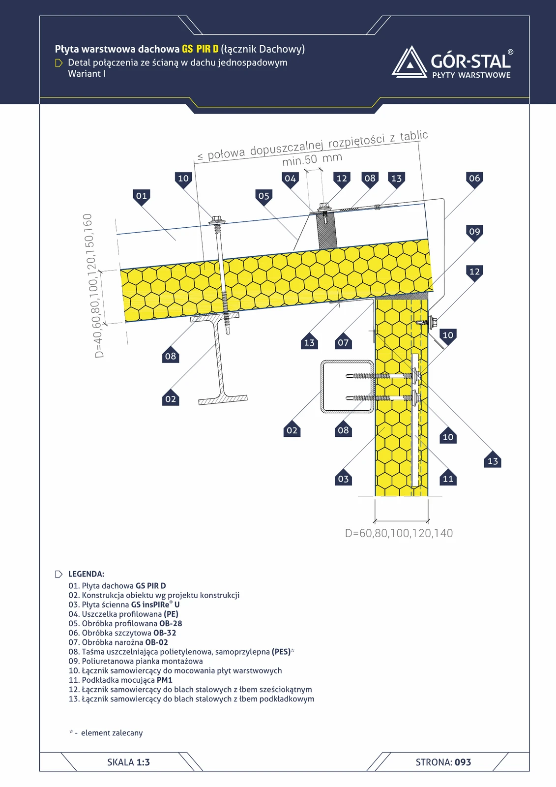
Monopitch roof + gable wall — variant I (GS PIR D)
Monopitch roof gable detail — connection of the roof panel to the gable wall. OB-32 gable flashing + OB-28 profiled flashing + PE profiled gasket. Premium aesthetics with PM1 in U wall panels.
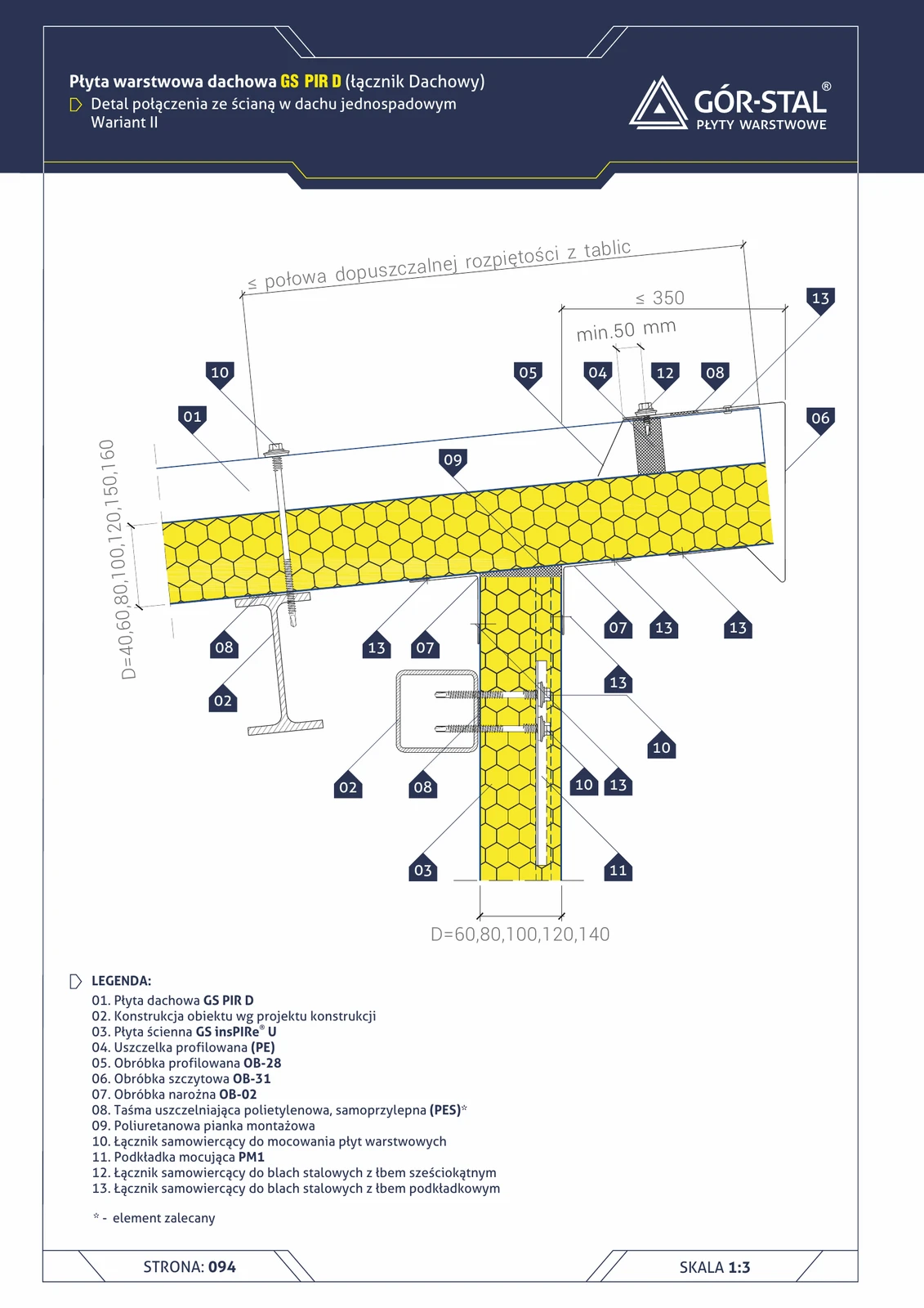
Monopitch roof + gable wall — variant II (GS PIR D)
Variant II of the gable with OB-31 gable flashing and overlap ≤350 mm. Alternative to variant I — different cover geometry, the same tightness result.
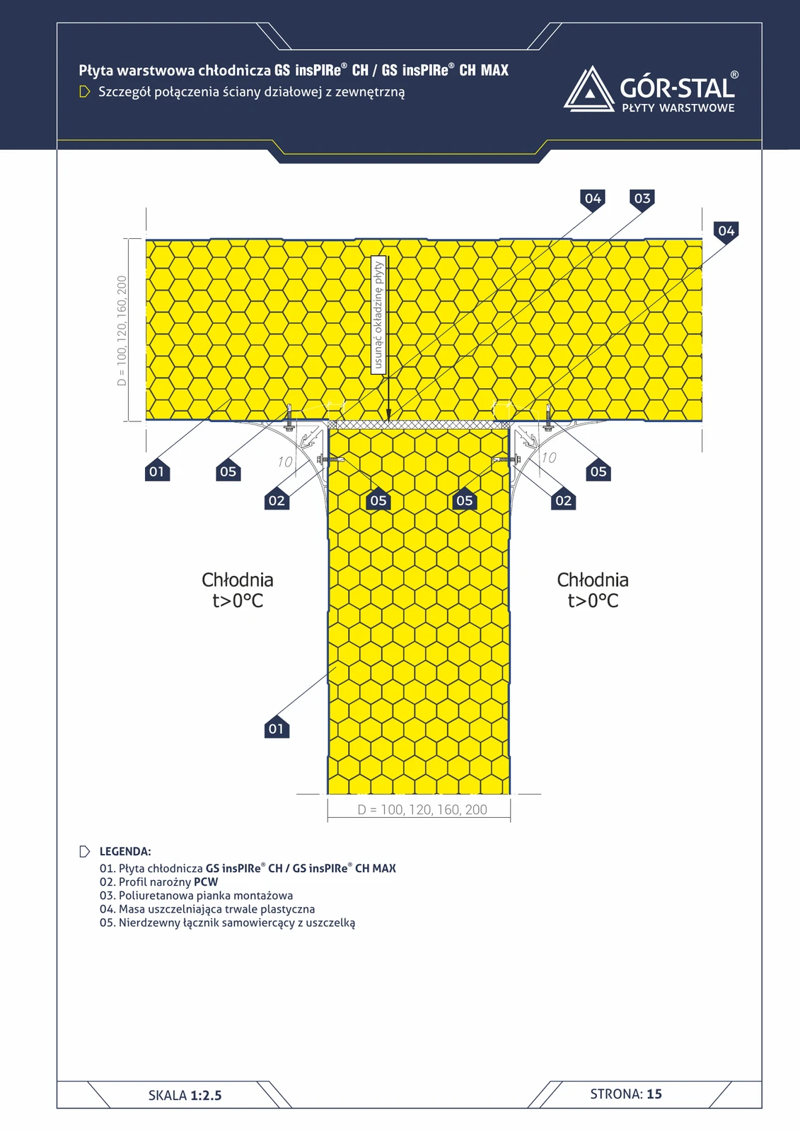
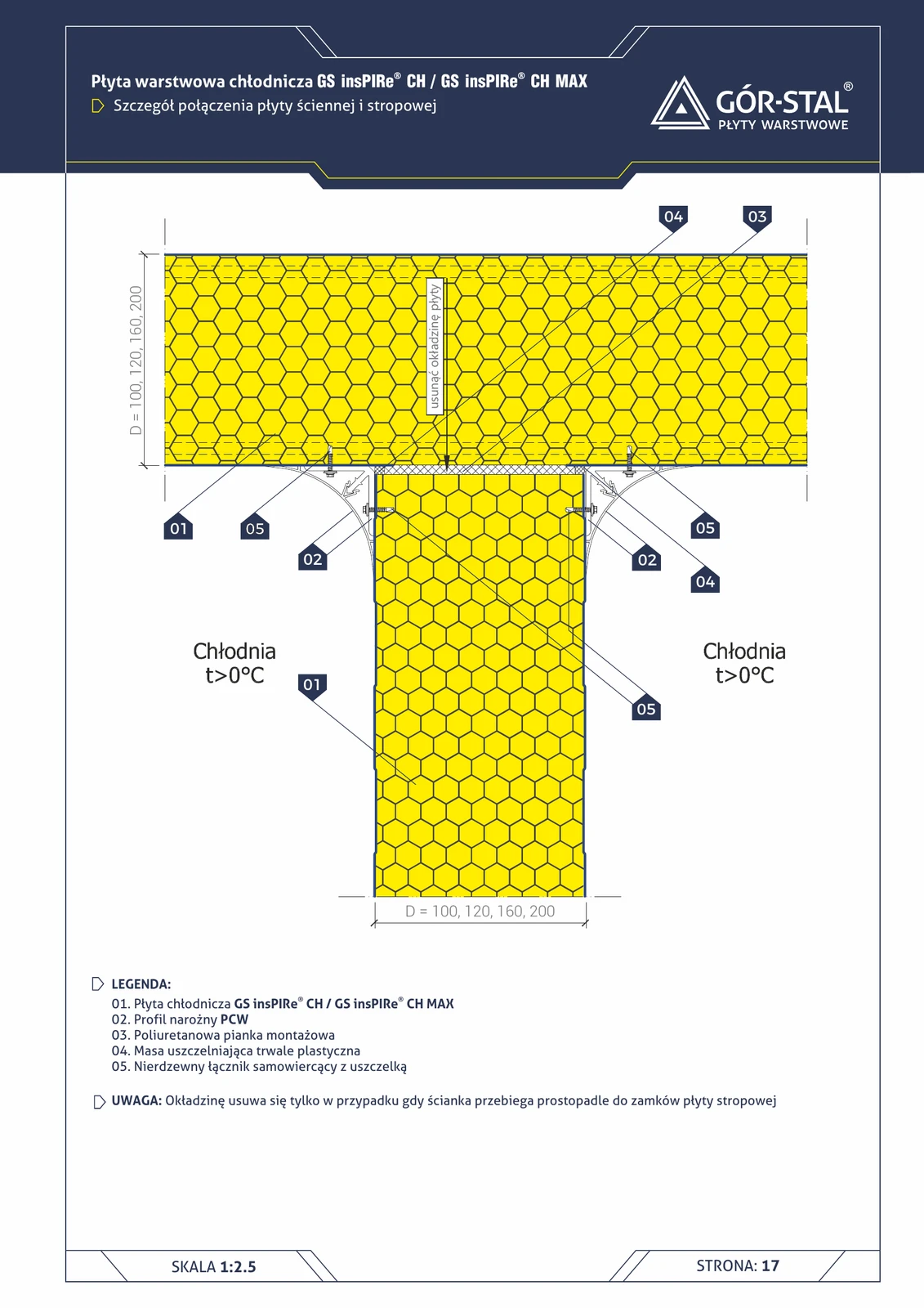
Partition wall to exterior wall connection — cold room
T-shaped junction connecting the partition wall to the exterior wall in a cold room (t > 0°C). Partition wall facing **removed** in the joint zone for improved tightness and thermal bridge elimination.
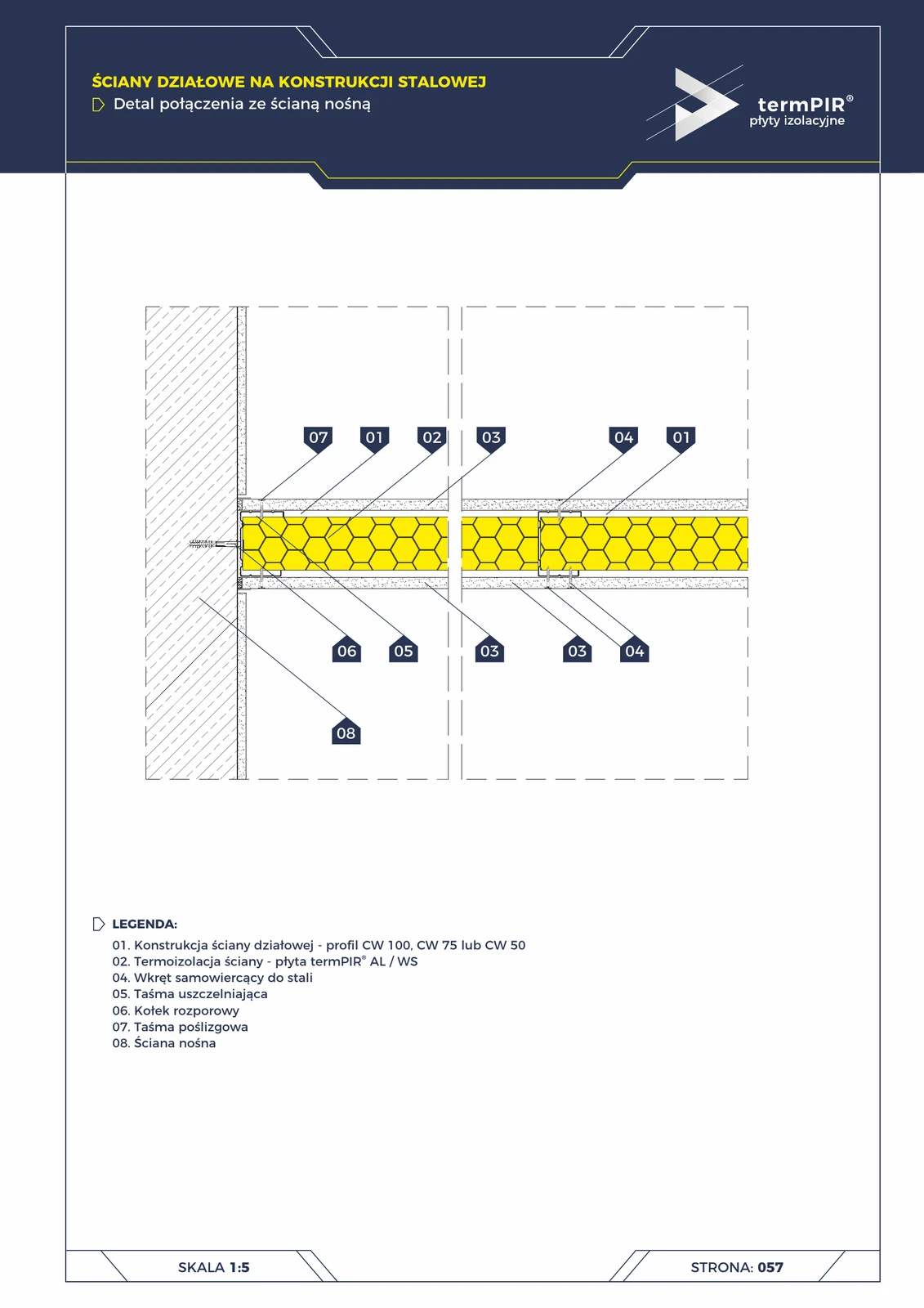
Partition wall — connection to load-bearing wall
Lightweight partition wall on CW steel framing (Knauf/Rigips) joined to a load-bearing wall. CW profile anchored through slip tape — accommodates differential thermal movement between load-bearing and partition wall. termPIR® AL infill provides thermal insulation + acoustic absorption.
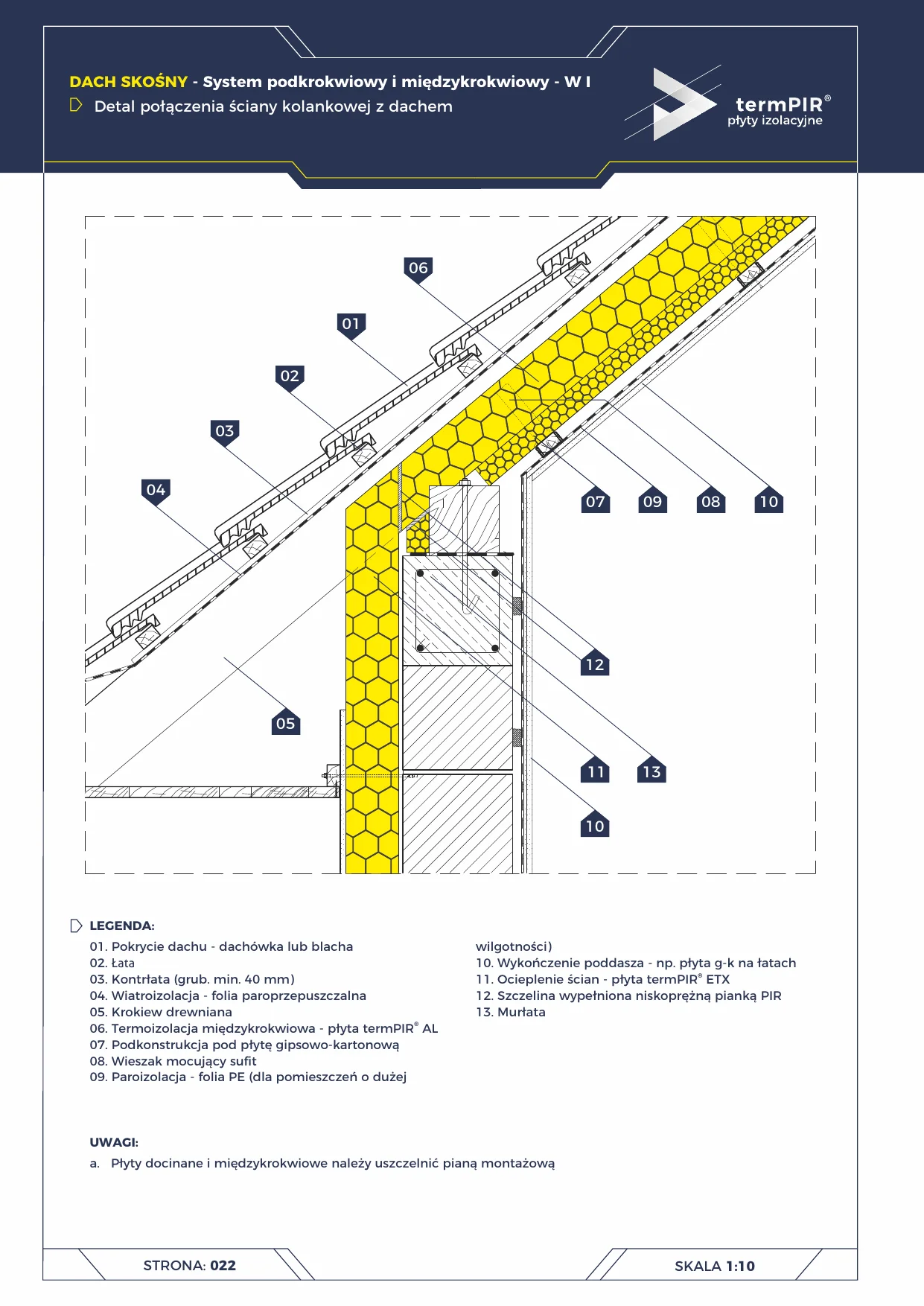
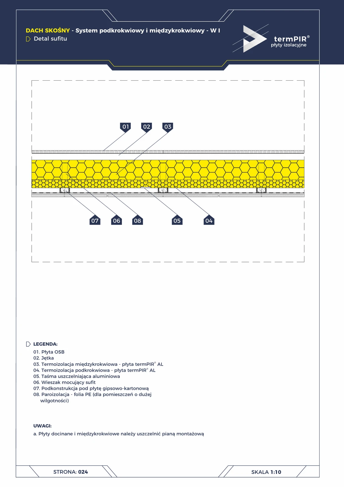
Between-rafter roof — knee wall junction
Connection detail between the knee wall and a pitched roof in the W I between-rafter/under-rafter termPIR system. The most critical thermal bridge in a single-family house.
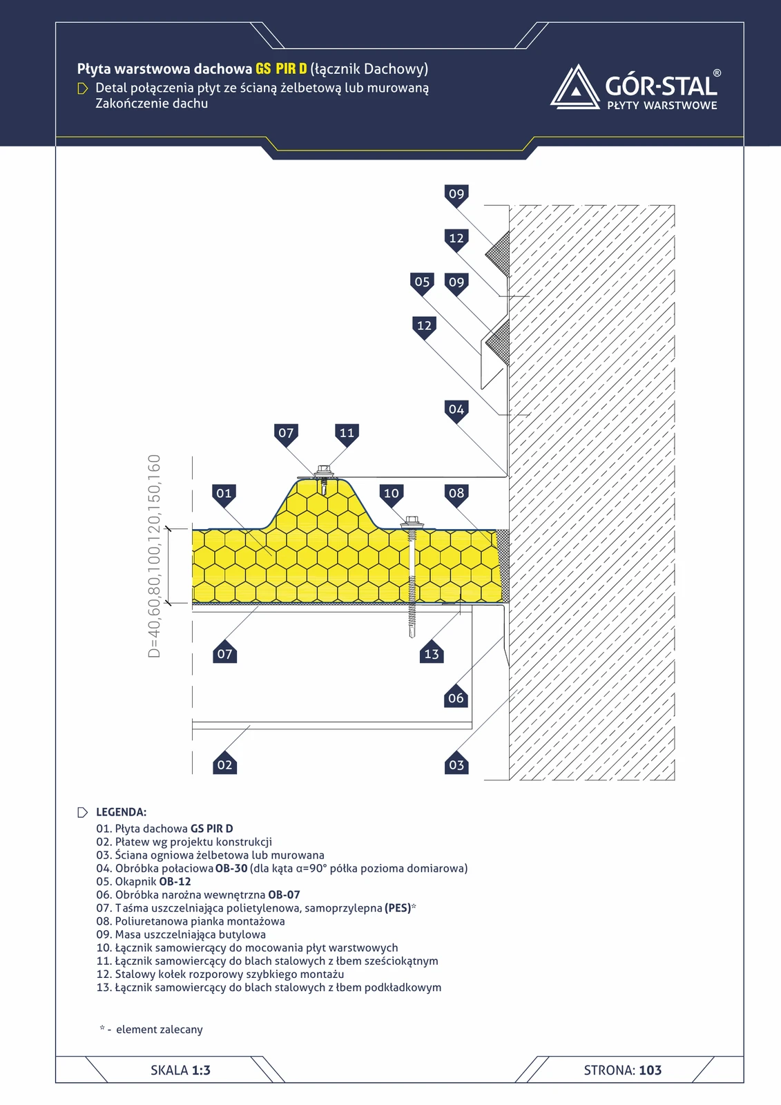
RC wall — roof termination (GS PIR D)
Roof termination detail at fire wall. OB-30 roof flashing + OB-12 drip edge + OB-07 corner trim + butyl seals and assembly foam.
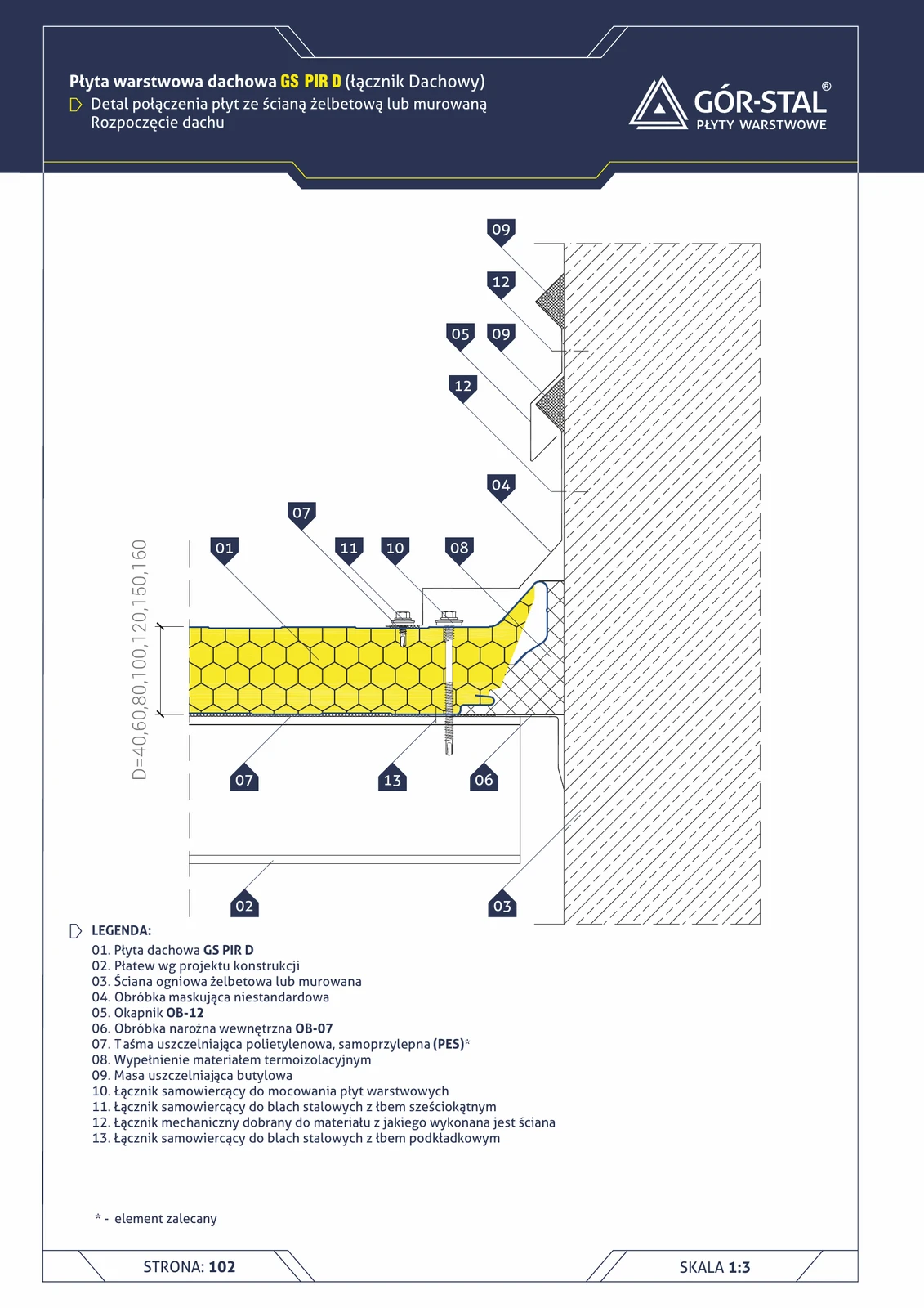
RC wall — roof start (GS PIR D)
Roof start detail at a reinforced concrete fire wall (e.g. inter-segment wall in twin halls). Custom masking flashing + OB-12 drip edge + OB-07 corner + thermal insulation infill.
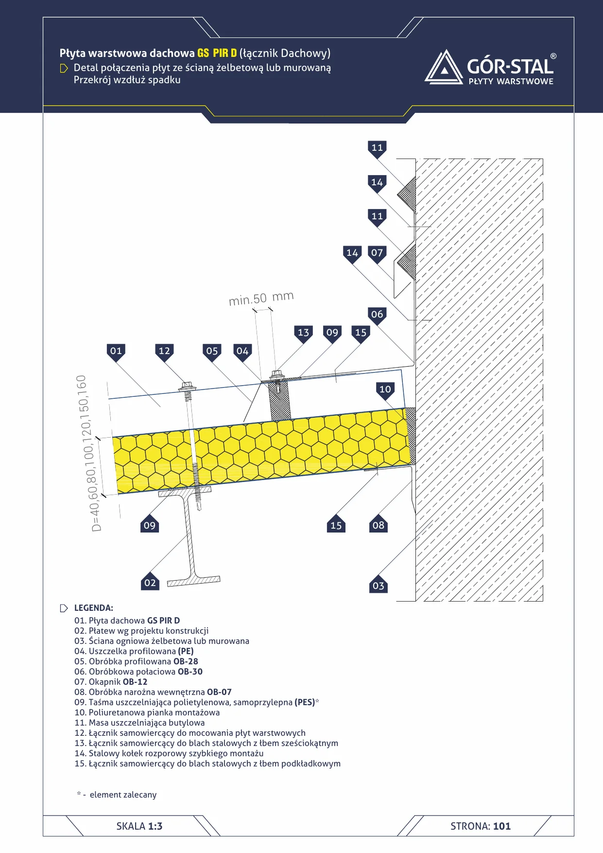
Roof to RC wall junction (along the slope)
Detail of GS PIR D roof panel junction with a masonry or reinforced concrete fire wall along the slope of the roof. Standard solution for halls with full-height RC parapets (fire protection).

Top floor ceiling — wall plate junction
termPIR insulation continuity at the ceiling / wall plate / knee wall triangle. Critical point for eliminating thermal bridges in unused attic eaves.
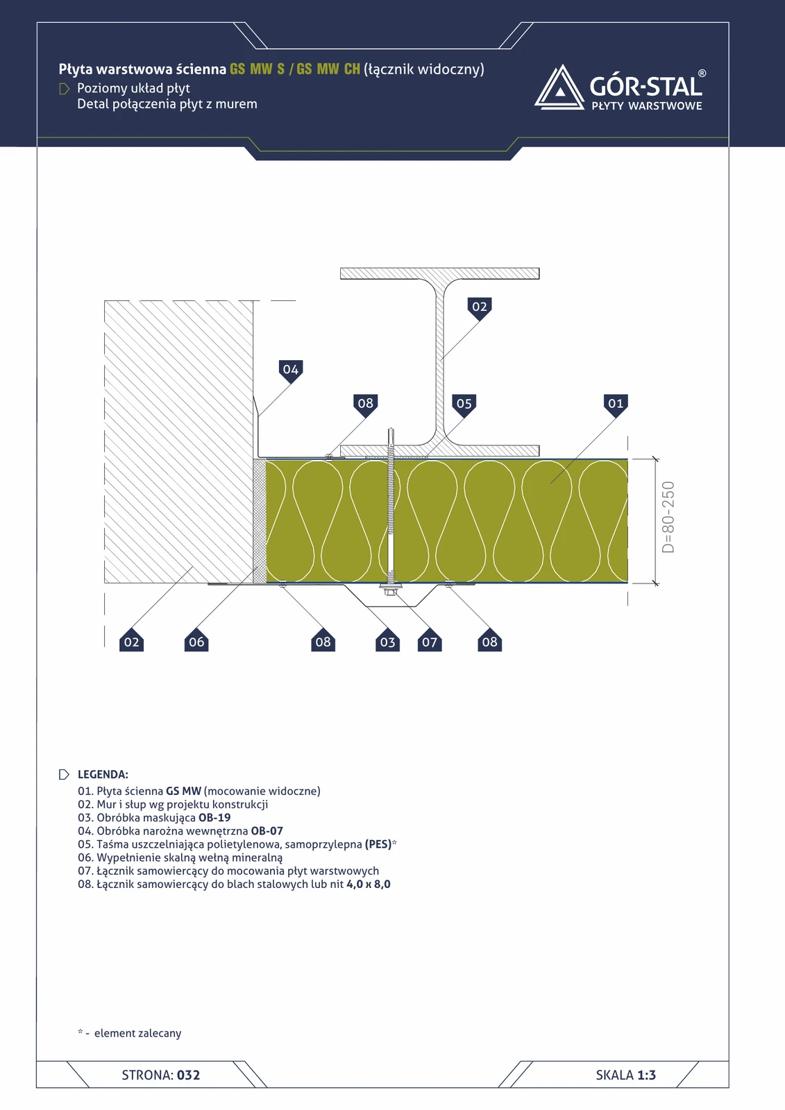
Wall junction — horizontal GS MW S/CH panel layout
Connection of horizontal sandwich panels to masonry / reinforced concrete wall — analogous to vertical layout (p. 23), with different panel fixing geometry. OB-19 flashing + OB-07 internal corner + mineral wool in the gap.
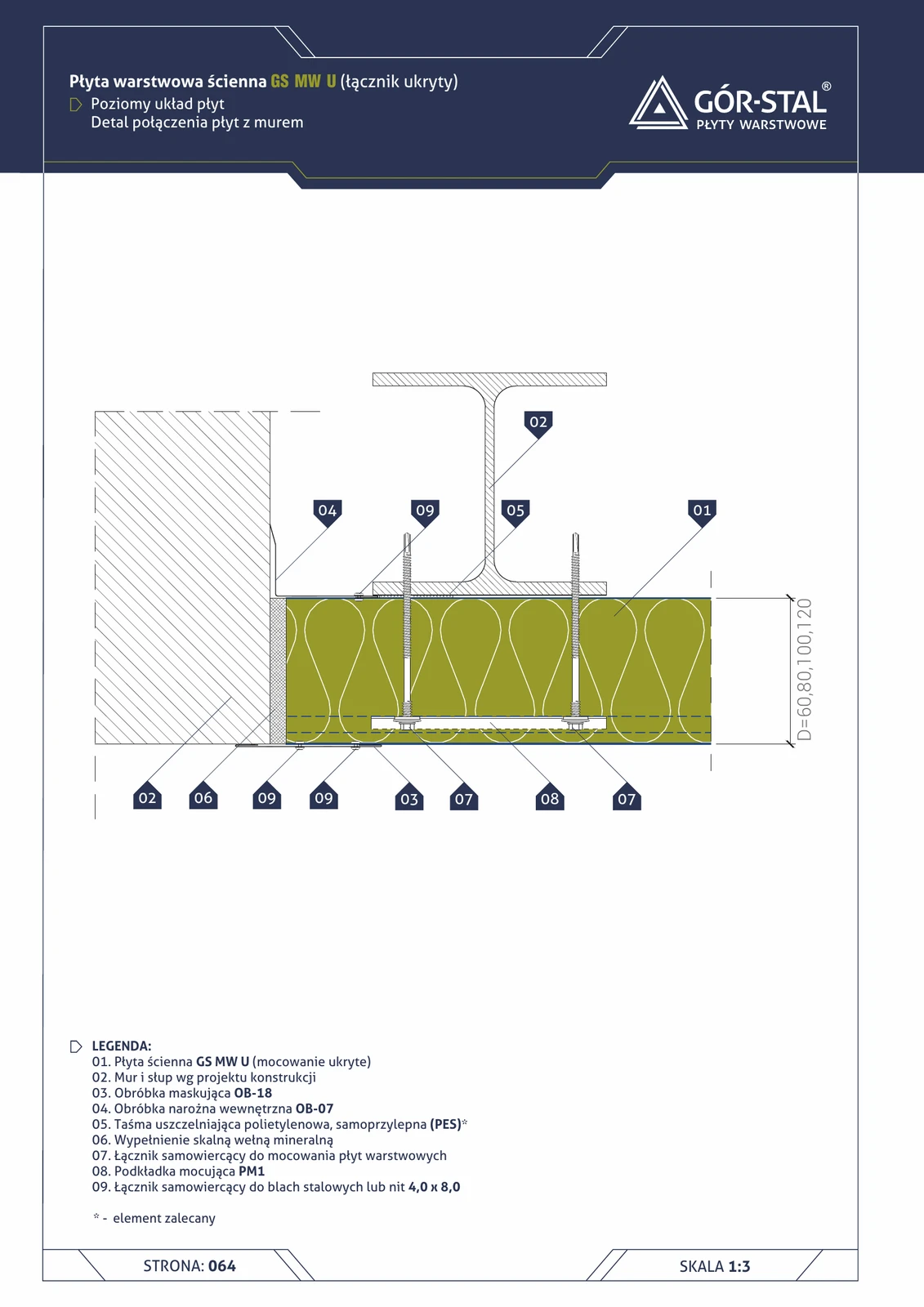
Wall junction — horizontal GS MW U panel layout
Connection of horizontal GS MW U panels with structural wall. OB-18 cover flashing (instead of OB-19 in S/CH) + OB-07 internal corner flashing + mineral wool in the gap.
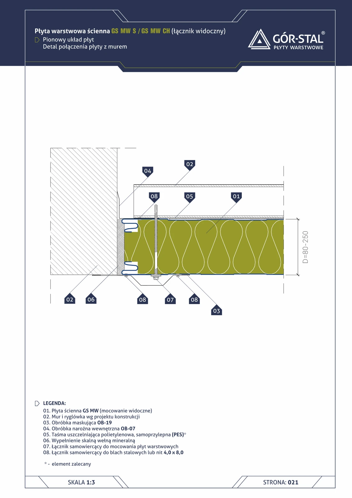
Wall junction — vertical GS MW S/CH panel layout
Detail of sandwich panel connection to masonry / reinforced concrete wall (e.g. fire wall, wall of existing hall, administrative wall in office block adjacent to hall). Internal OB-07 + cover OB-19 flashing + mineral wool in joint.
Wall junction — horizontal insPIRe® S panel layout
Connection of horizontal PIR panels to structural masonry. OB-19 external trim + OB-07 internal corner flashing + PURS expanding foam in the gap.
Wall junction — vertical insPIRe® S panel layout
Connection of vertical PIR panels to a structural wall (RC / brick). External OB-19 flashing + internal corner OB-07 + PURS expanding foam or sealing tape in the gap.

Wall junction — horizontal layout of insPIRe® U panels
Connection of horizontal premium PIR panels with structural masonry. OB-18 cover flashing (instead of OB-19 in S) + OB-07 internal + PM1.
Wall junction — vertical GS MW U panel layout
Connecting vertical GS MW U panels to a wall. Identical construction to S/CH (page 23) with one difference — concealed panel fixing. OB-19 cover flashing + OB-07 internal corner flashing + mineral wool in the gap.
Wall junction — vertical insPIRe® U panel layout
Connection of vertical premium PIR panels with structural masonry. OB-19 outside + OB-07 inside + PURS installation foam.
Ceiling (14)
Ceiling detail — under-rafter roof W1 (termPIR® AL × 2 layers)
Habitable attic ceiling in variant I of the under-rafter system. Two layers of termPIR® AL insulation: the first between the collar beams, the second suspended below them — continuation of the W1 roof logic at the ceiling level.
Ceiling Detail — Under-Rafter Roof W2 (termPIR® AL GK Under Collar Ties)
Variant II of the attic ceiling: instead of a separate termPIR® AL layer plus a separate plasterboard under the collar ties, we use a single termPIR® AL GK composite board with factory-bonded plasterboard. Fewer joints, single fastening.
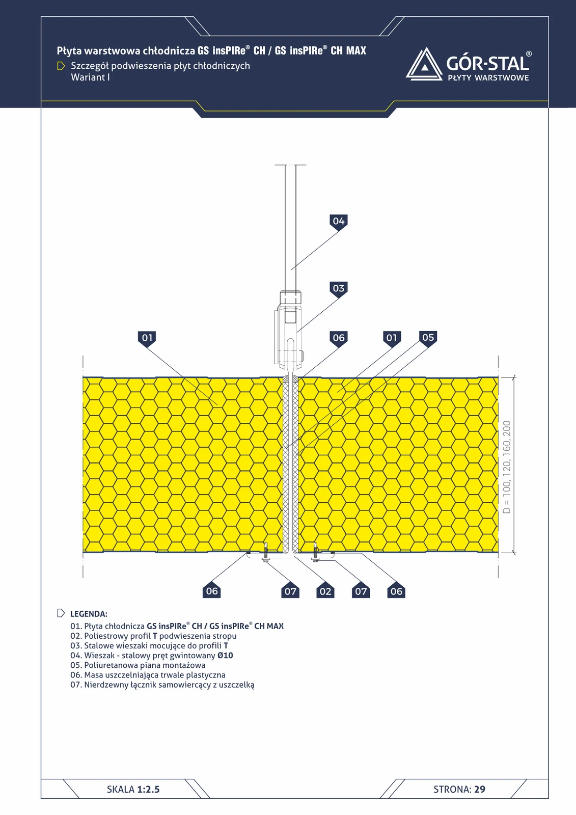
Cold-store panel suspension — Variant I (T-profiles)
Cold-store ceiling suspended on **polyester T-profiles** with steel hangers on Ø10 threaded rod. Flexible solution with thermal insulation within the polyester profile.
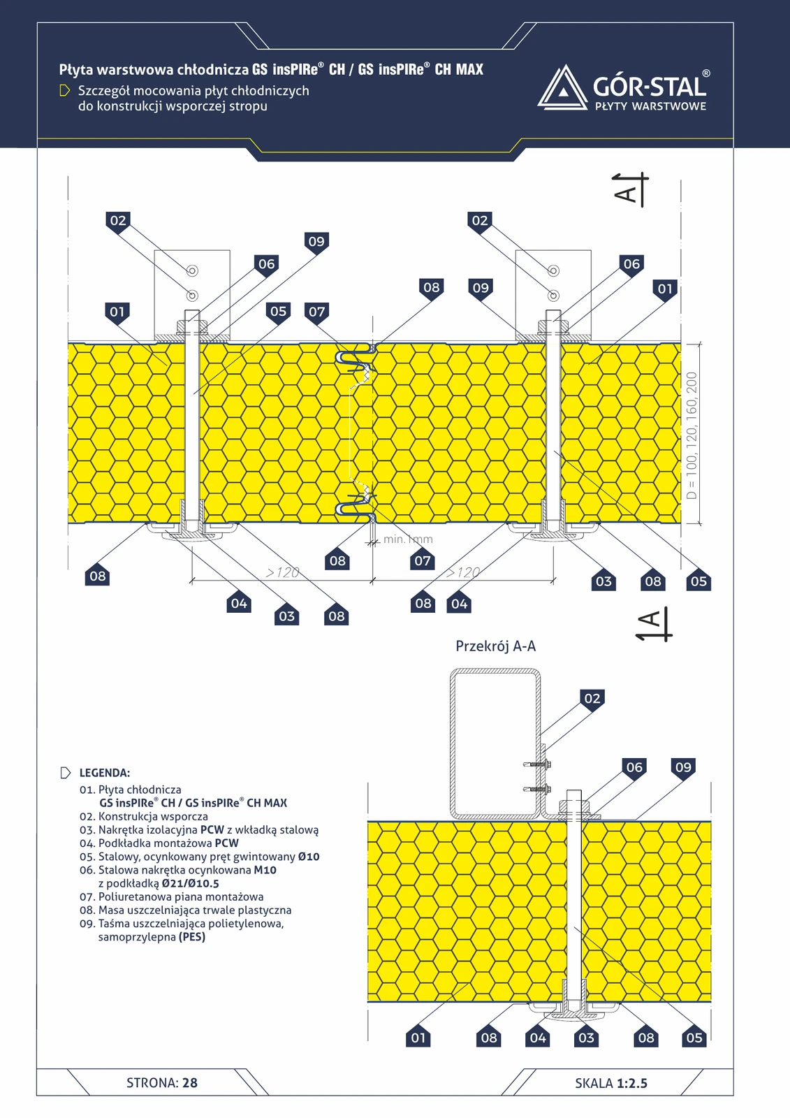
Fixing CH ceiling panels to the supporting structure
Horizontal cross-section + A-A of cold-storage ceiling panel fixing to the supporting beam. **Thermal-break PVC fastener system + Ø10 threaded rod** — identical to freezer wall fixing (p. 25).
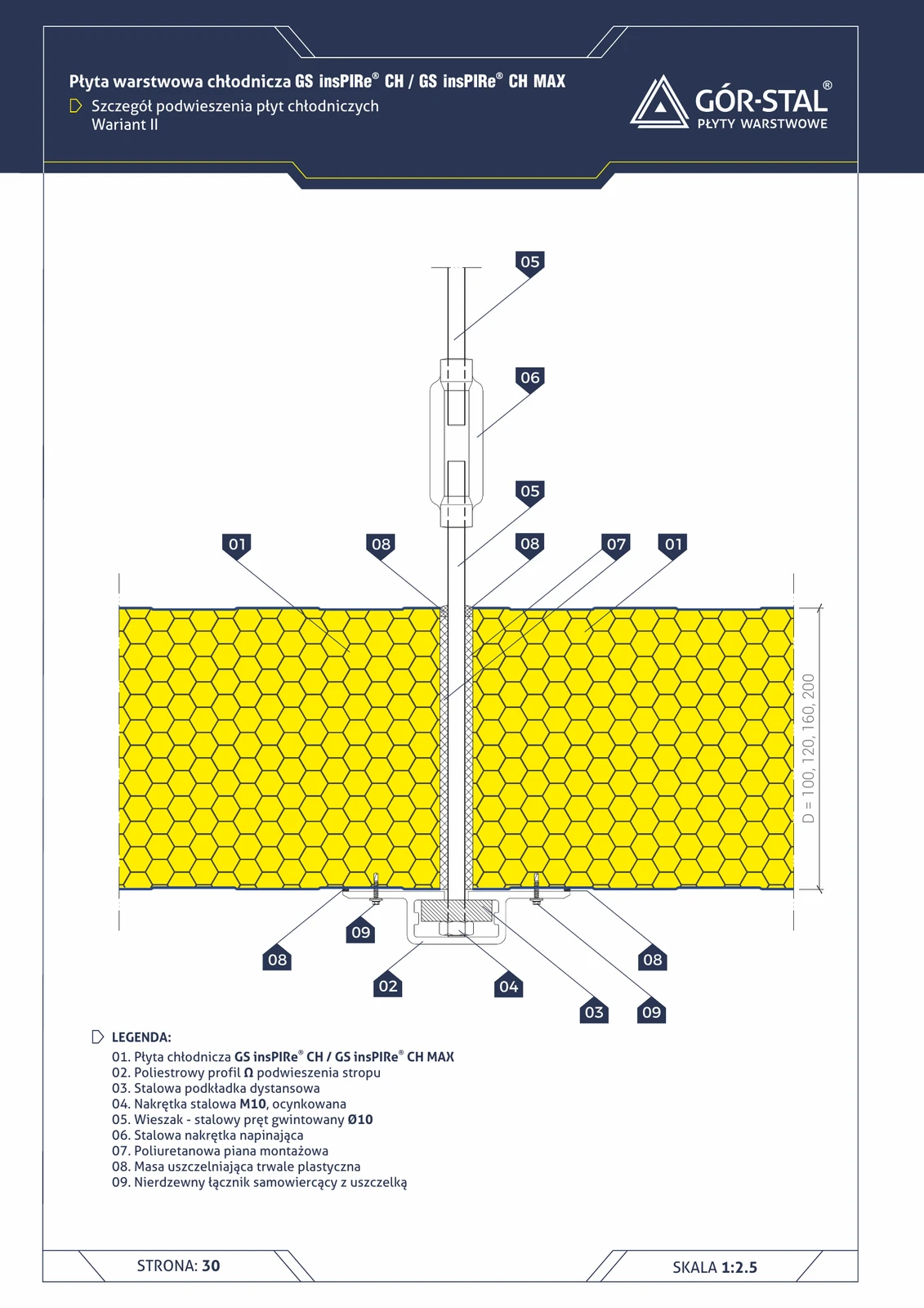
Cold store panel suspension — Variant II (Ω profiles)
Alternative suspension method: **polyester Ω profiles + turnbuckle** on a Ø10 rod. Provides **height adjustment** during installation and more precise ceiling alignment.
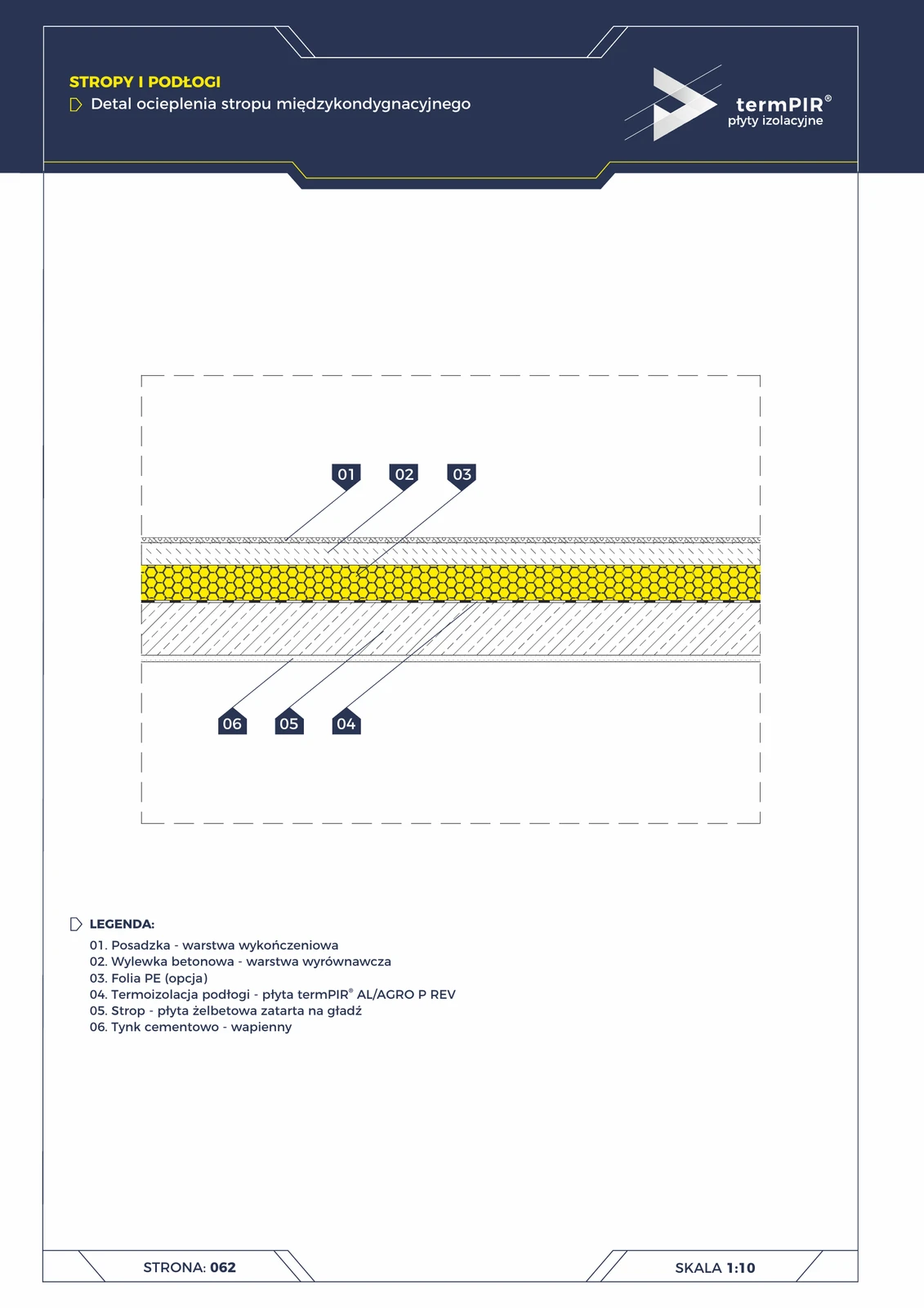
Intermediate floor (termPIR® AL acoustic)
Thermal and acoustic insulation of the floor between storeys. termPIR® AL board laid on reinforced concrete creates a 'floating floor' — eliminates transmission of impact sounds between floors (Ln,w reduction of 18–22 dB).
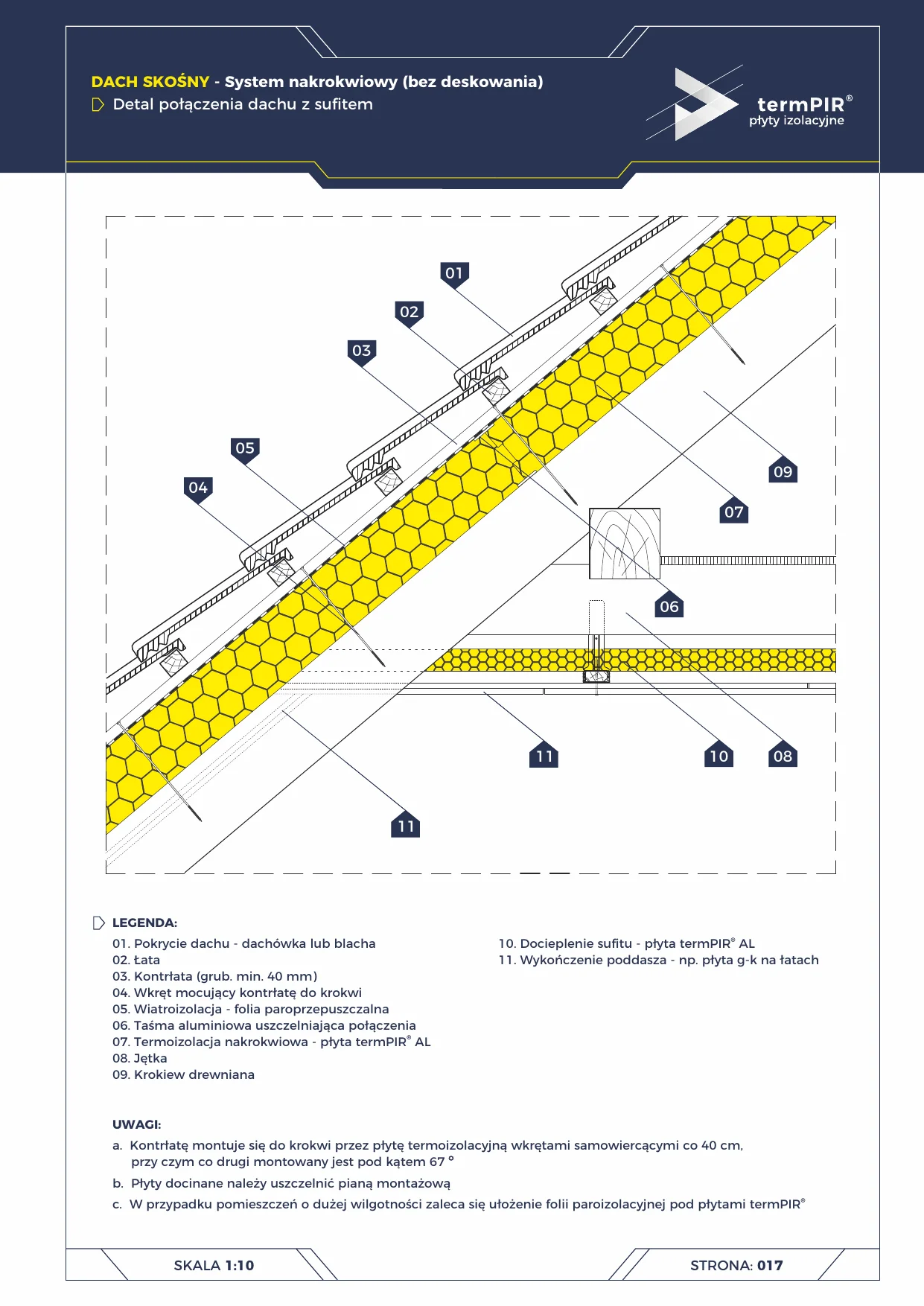
Over-rafter roof — ceiling junction
Junction detail of over-rafter pitched roof with flat ceiling under collar beam in termPIR AL. Insulation runs above the rafters — rafters remain exposed from inside, timber thermal bridge eliminated.
Partition wall to ceiling connection — cold store
T-junction connecting a partition wall with the ceiling in **two adjacent cold rooms** (both t > 0°C). Facing is removed **only when the partition runs perpendicular** to the ceiling. PVC profile + PUR foam + plastic sealant.
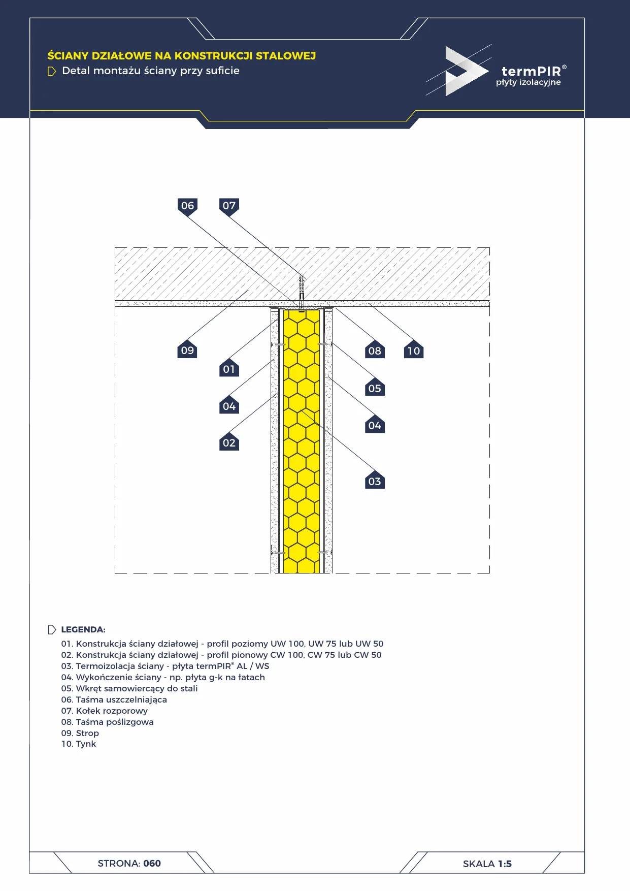
Partition Wall — Ceiling Mount
Mounting detail of a stud partition wall with termPIR insulation at the ceiling. Sliding tape eliminates wall cracking under slab deflection.
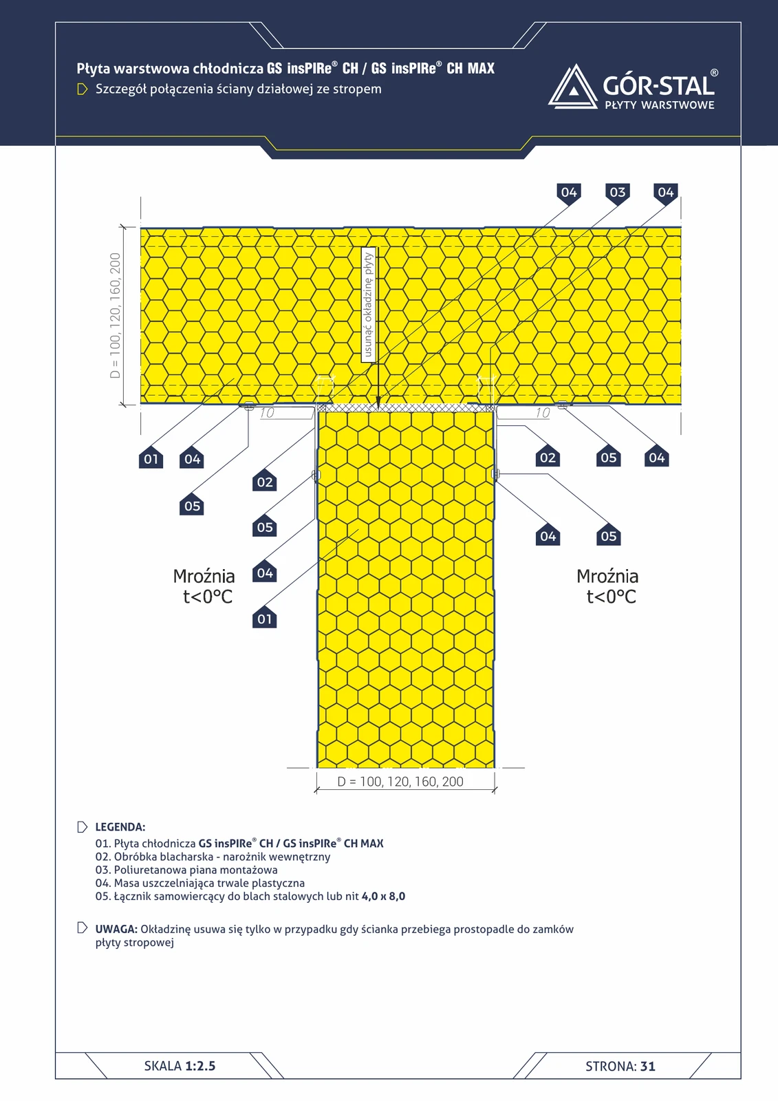
Partition wall to ceiling connection — freezer
T-junction connecting partition wall with ceiling in a freezer room (t < 0°C). Facing removal only when the wall is **perpendicular** to the ceiling. Internal OB-02 + 3-layer sealing.
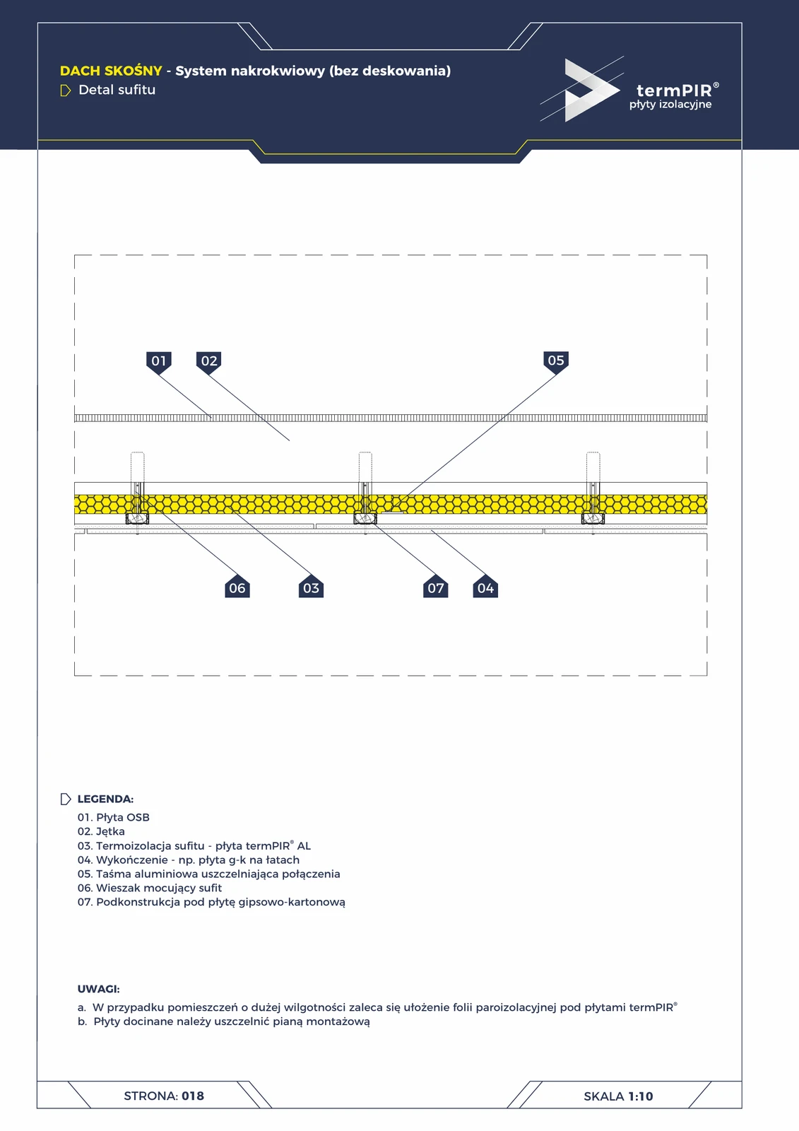
Ceiling detail — over-rafter roof (termPIR® AL between collar ties)
Habitable attic ceiling in the over-rafter system. termPIR® AL boards laid directly between collar ties of the timber ceiling, OSB as upper sheathing, steel substructure suspended on hangers + plasterboard as finish.
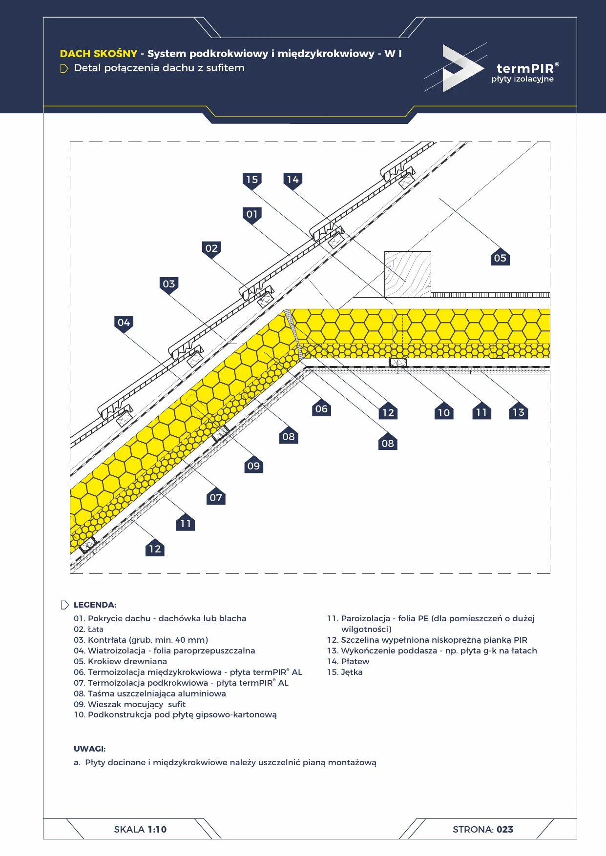
Under-rafter roof — ceiling junction
Junction detail of pitched roof with flat ceiling below the collar beam in the W I termPIR under-rafter system. Two-layer insulation: between-rafter + under-rafter = complete elimination of the rafter thermal bridge.
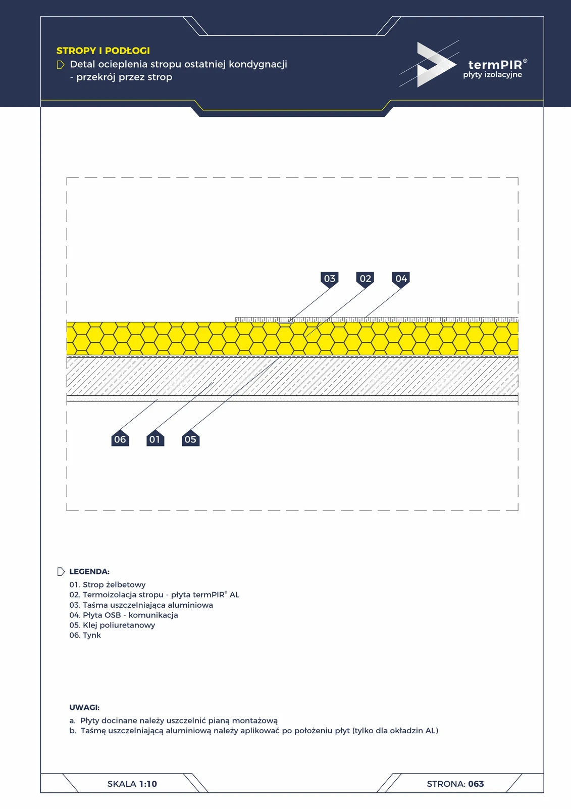
Top floor ceiling — termPIR® AL (section)
Insulation of the ceiling beneath an unused attic — an alternative to insulating the roof slope. termPIR® AL board bonded to reinforced concrete with PUR foam adhesive, aluminium tape sealing the joints, OSB as walking surface. A cheaper and simpler option vs. over-rafter / under-rafter roof insula
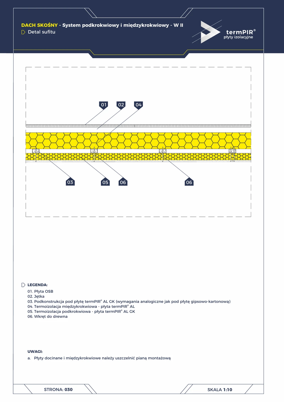
W2 roof to ceiling junction (termPIR® AL GK)
Junction between pitched roof and horizontal attic ceiling in the W2 system. termPIR® AL GK board continues from roof onto collar tie — shared plasterboard finish with acrylic sealant for a clean corner.
Floor (4)
Cold room partition wall — installation at floor
Detail of partition wall at cold room floor zone (t > 0°C) with termPIR sub-floor system and vapour barrier. PVC trim + stainless self-drilling fasteners with gasket.
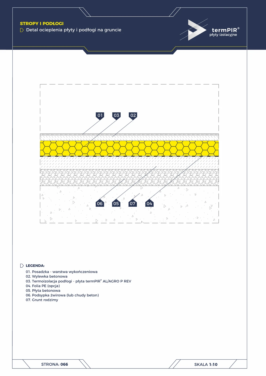
Ground floor slab (termPIR® AL)
Classic ground floor insulation without basement. termPIR® AL board on concrete slab with separating PE film, gravel bedding ensures capillary water drainage. Standard for 90% of new single-family homes in Poland.
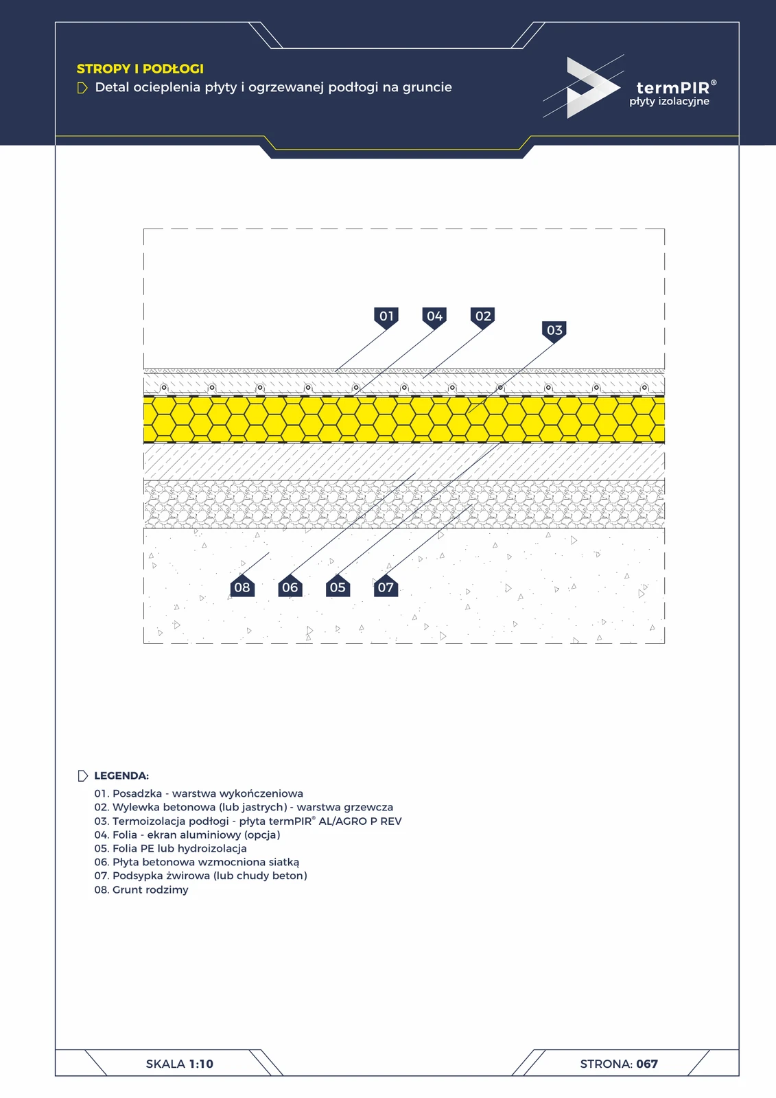
Heated floor on ground (termPIR® AL + reflector)
Variant with water-based underfloor heating. Critical addition: aluminium reflector above termPIR® increases heating efficiency by 8-12% (redirects thermal radiation upwards). Standard for modern passive houses.
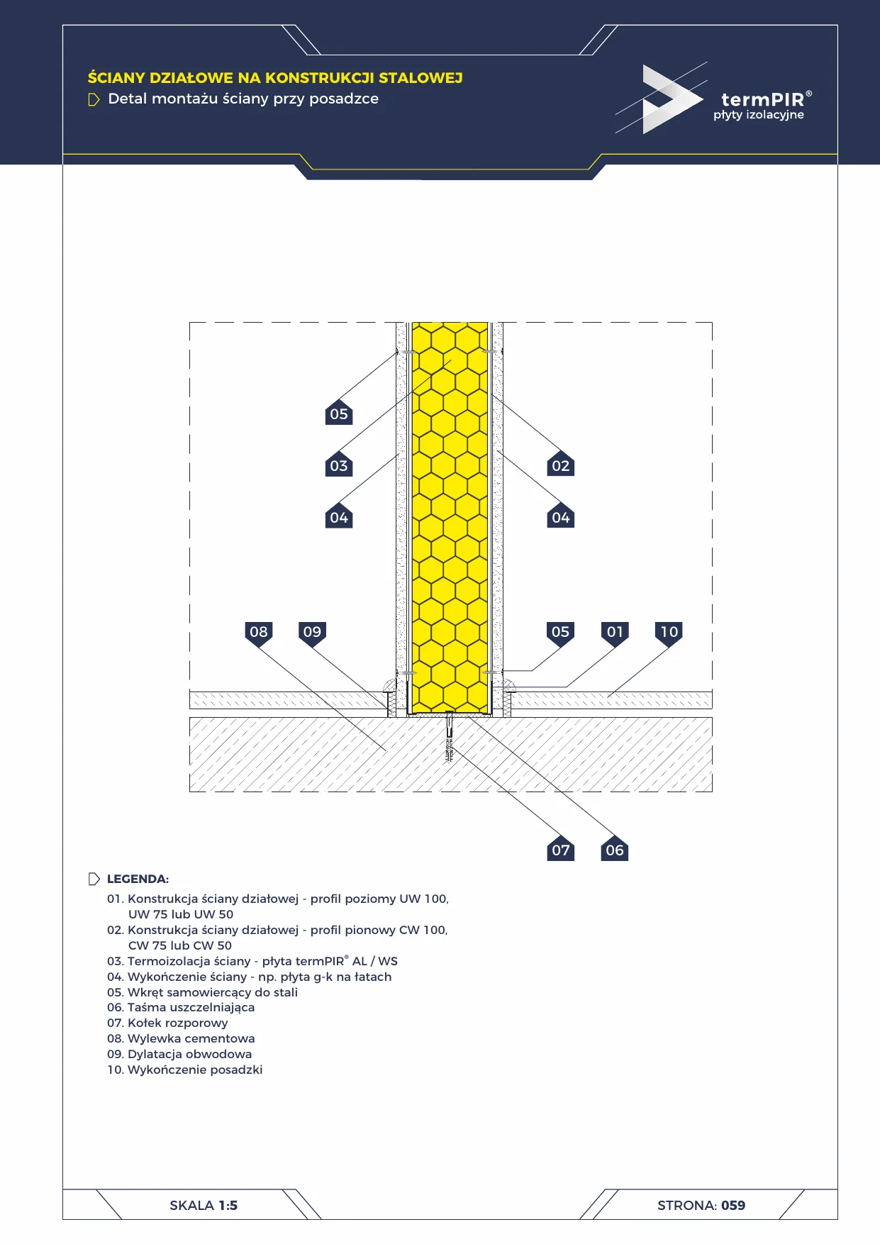
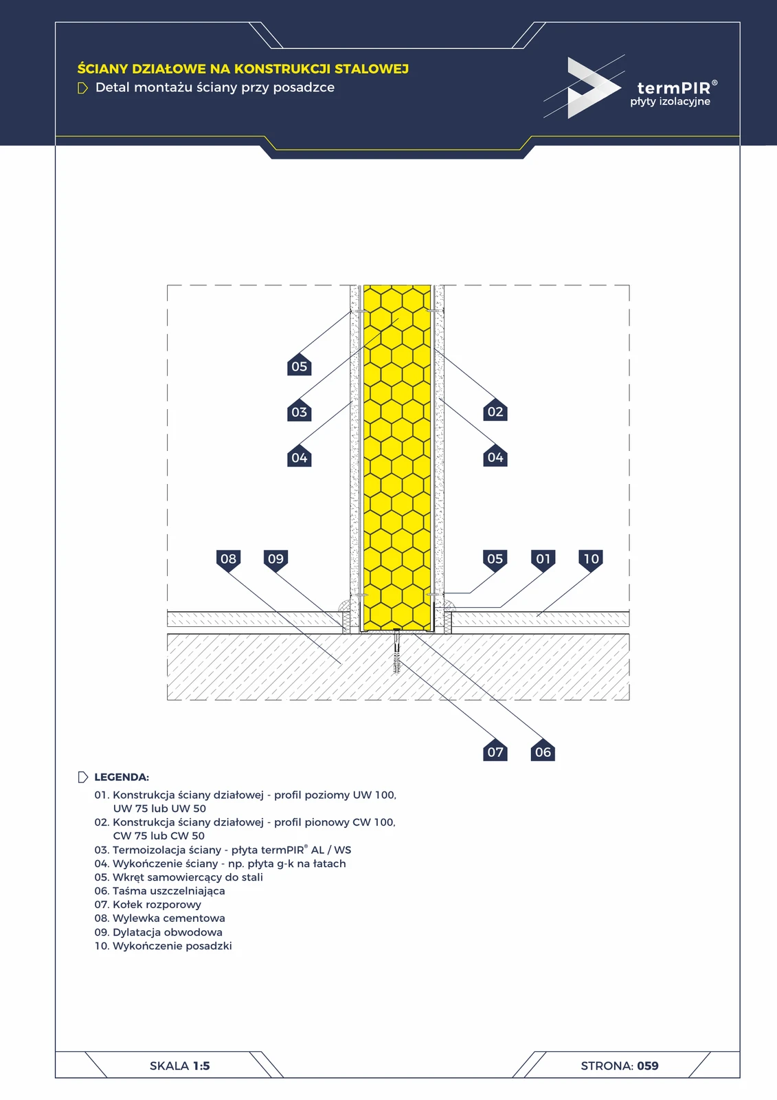
Partition wall — floor mounting
Mounting detail of a stud partition wall with termPIR insulation at the floor. Perimeter expansion joint eliminates acoustic bridges between rooms.
Other details (53)
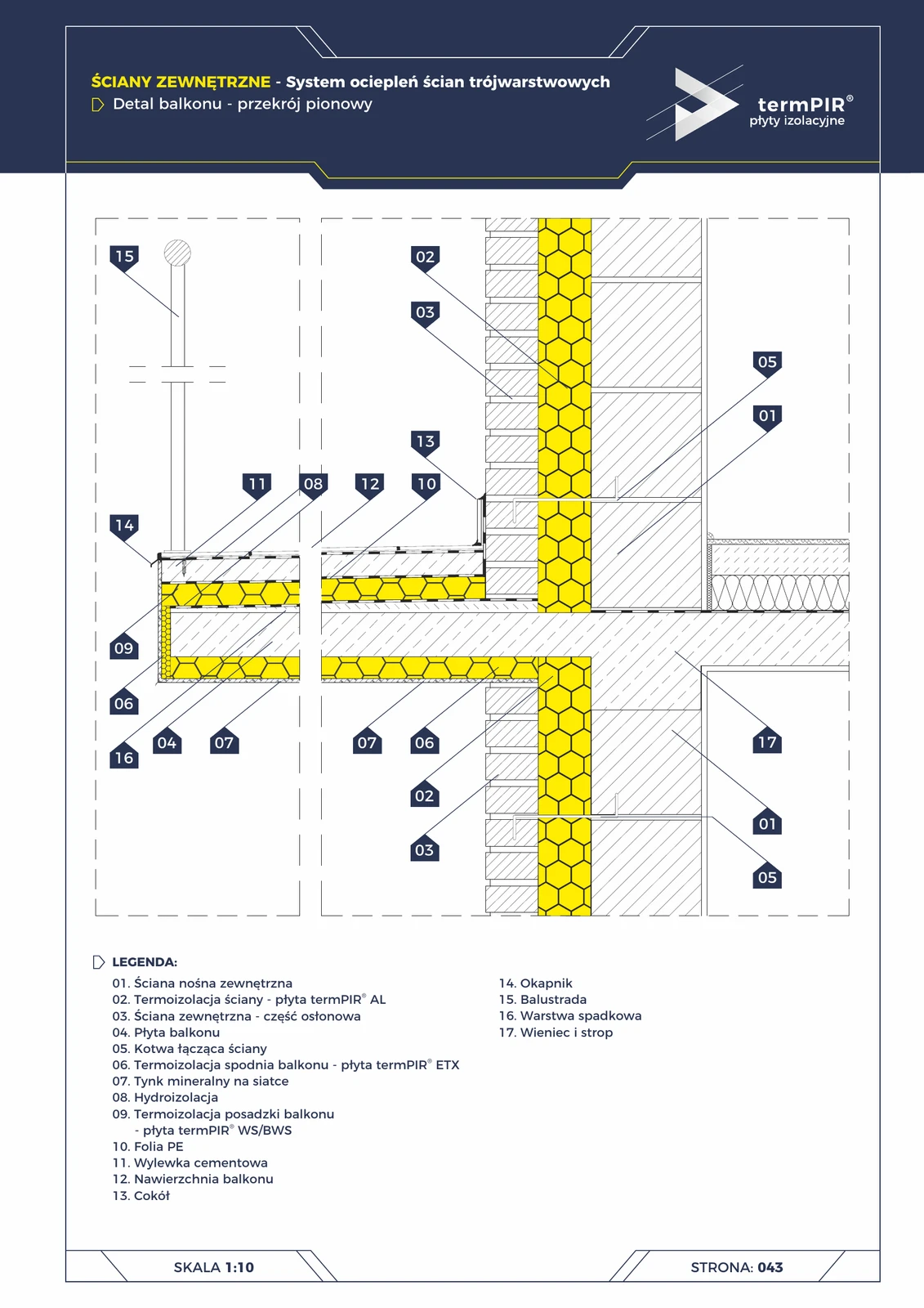
Balcony in three-layer wall (termPIR® AL + ETX + WS)
Detail of a balcony recessed into a three-layer wall. Three layers of PIR insulation in different locations: AL (main wall), ETX (balcony soffit, balcony fascia), WS (under the balcony floor — waterproof). Linear thermal bridge elimination ψ ≈ 0.8 → <0.1 W/m·K.
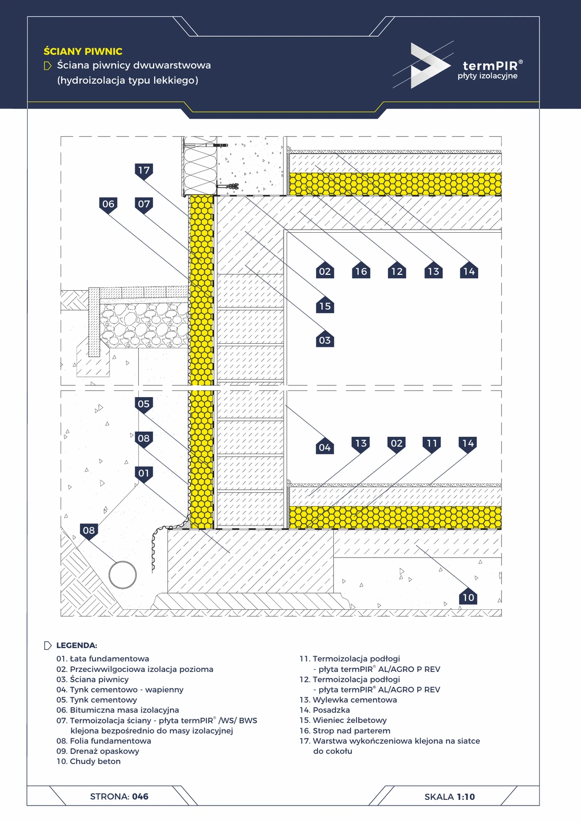
Two-layer basement wall (termPIR® WS + AL floor)
Full basement of a single-family house: termPIR® WS externally on bituminous coating + termPIR® AL beneath the basement floor screed. Perimeter drainage + dimpled foundation membrane protect against groundwater pressure.
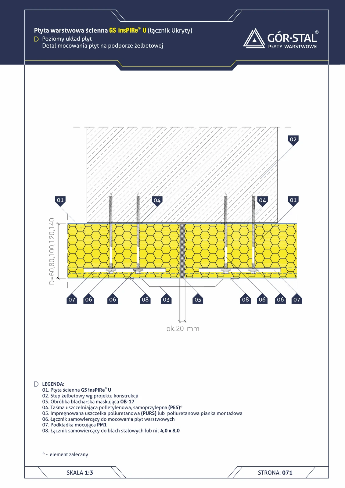
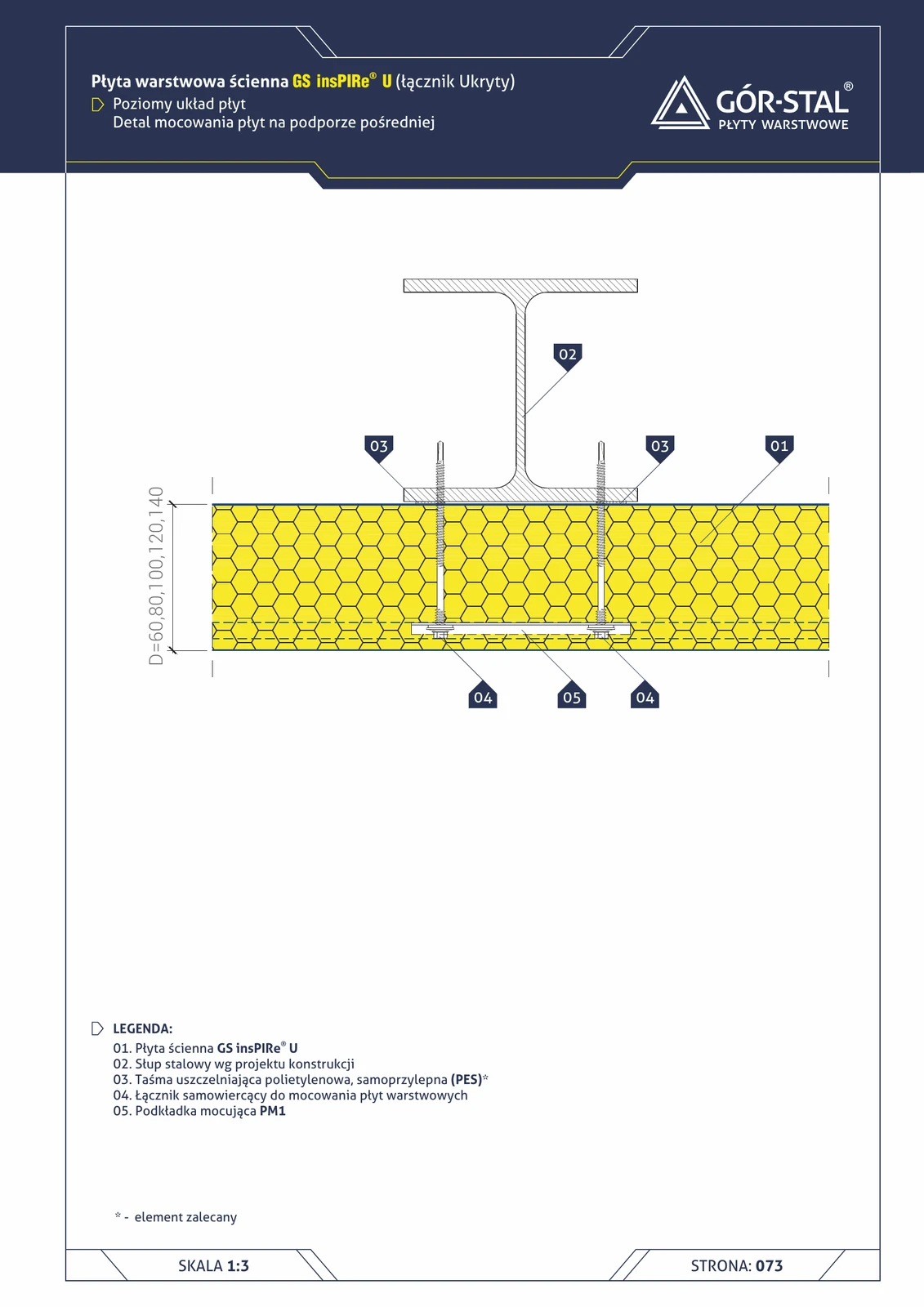
Concrete support — horizontal insPIRe® U panel layout
Premium fixing of horizontal PIR panels to RC column. Chemical or mechanical anchors, PM1 for U-lock, OB-17 cover flashing.
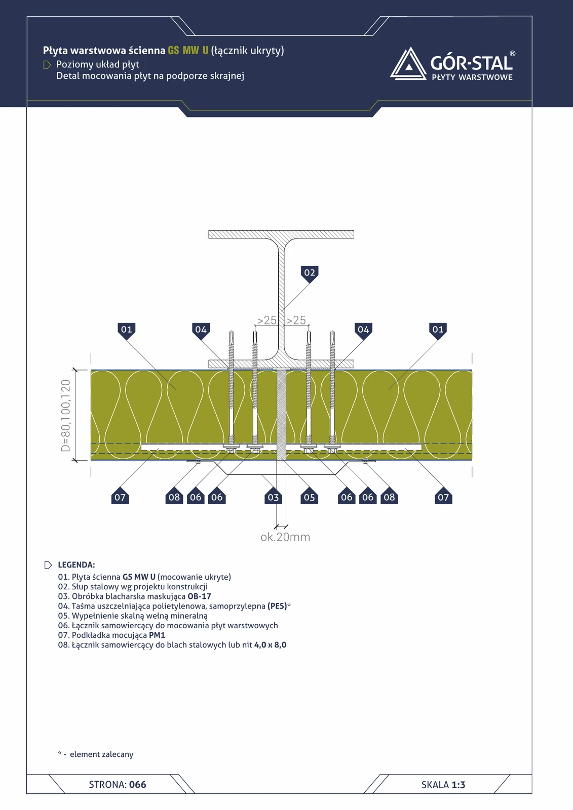
Edge support — horizontal GS MW U panel layout
Premium fixing of horizontal panels at the end column of a hall. Panels terminate at the column with a 20 mm gap, OB-17 conceals the joint, PM1 provides hidden fastening. End segment of long hall walls.
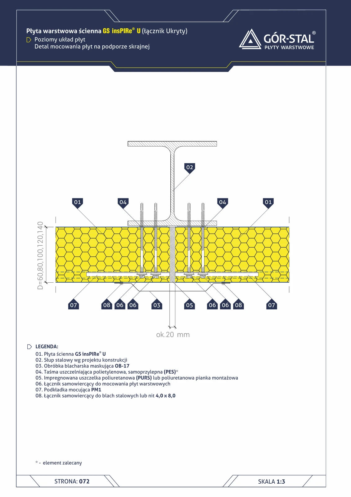
Edge support — horizontal insPIRe® U panel layout
Premium fixing of horizontal panels at the end column of the hall. OB-17 cover flashing + PM1 concealed fastening.
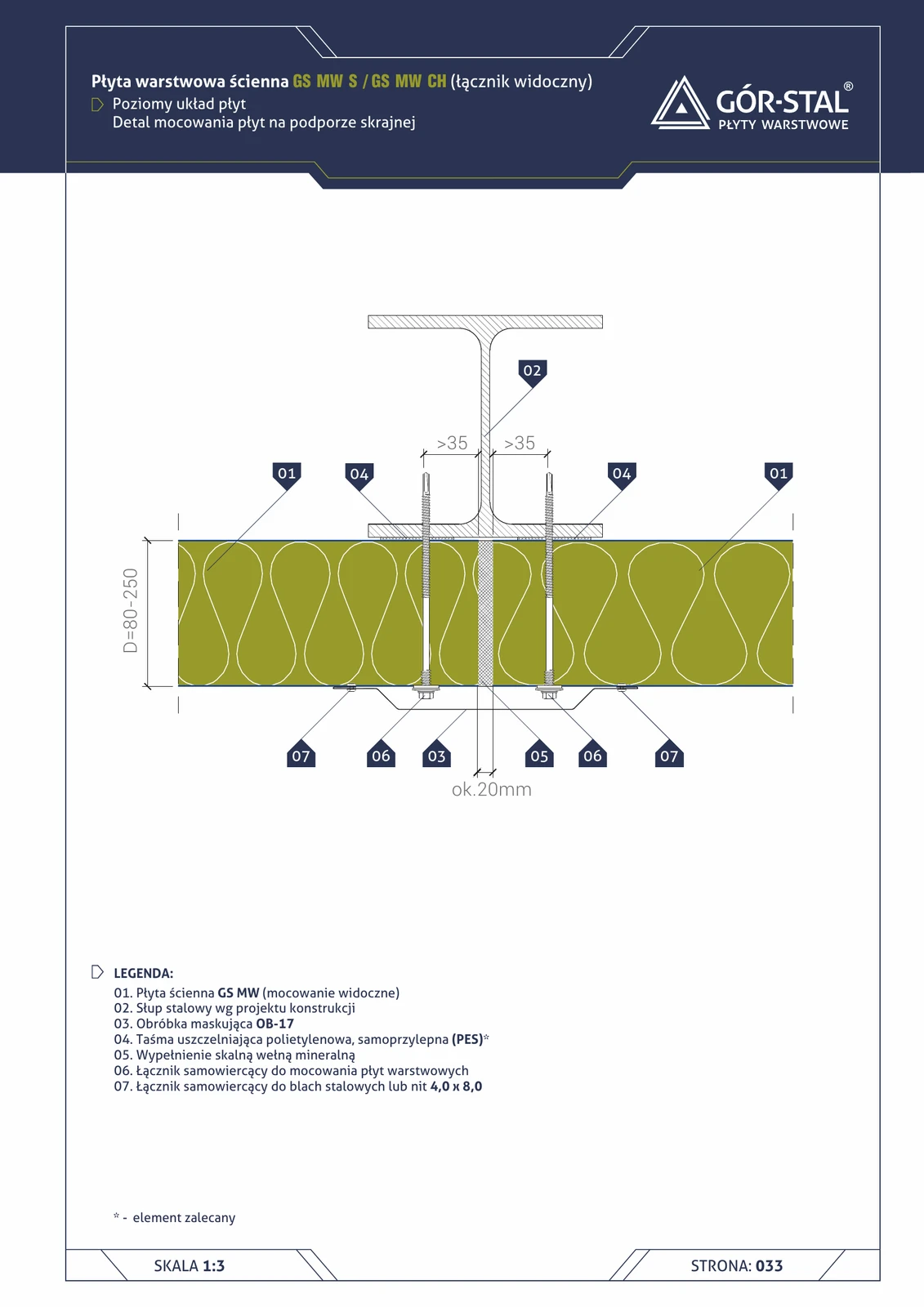
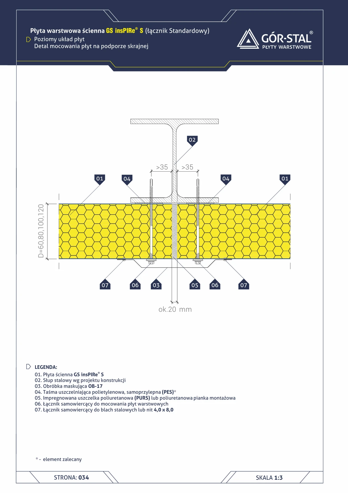
End support — horizontal layout of GS MW S/CH panels
Fixing of horizontally laid sandwich panels to an end support (terminal column of a hall). Panels terminate at the column with a ~20 mm gap, OB-17 flashing conceals the vertical joint. Typical for end segments of long hall walls.
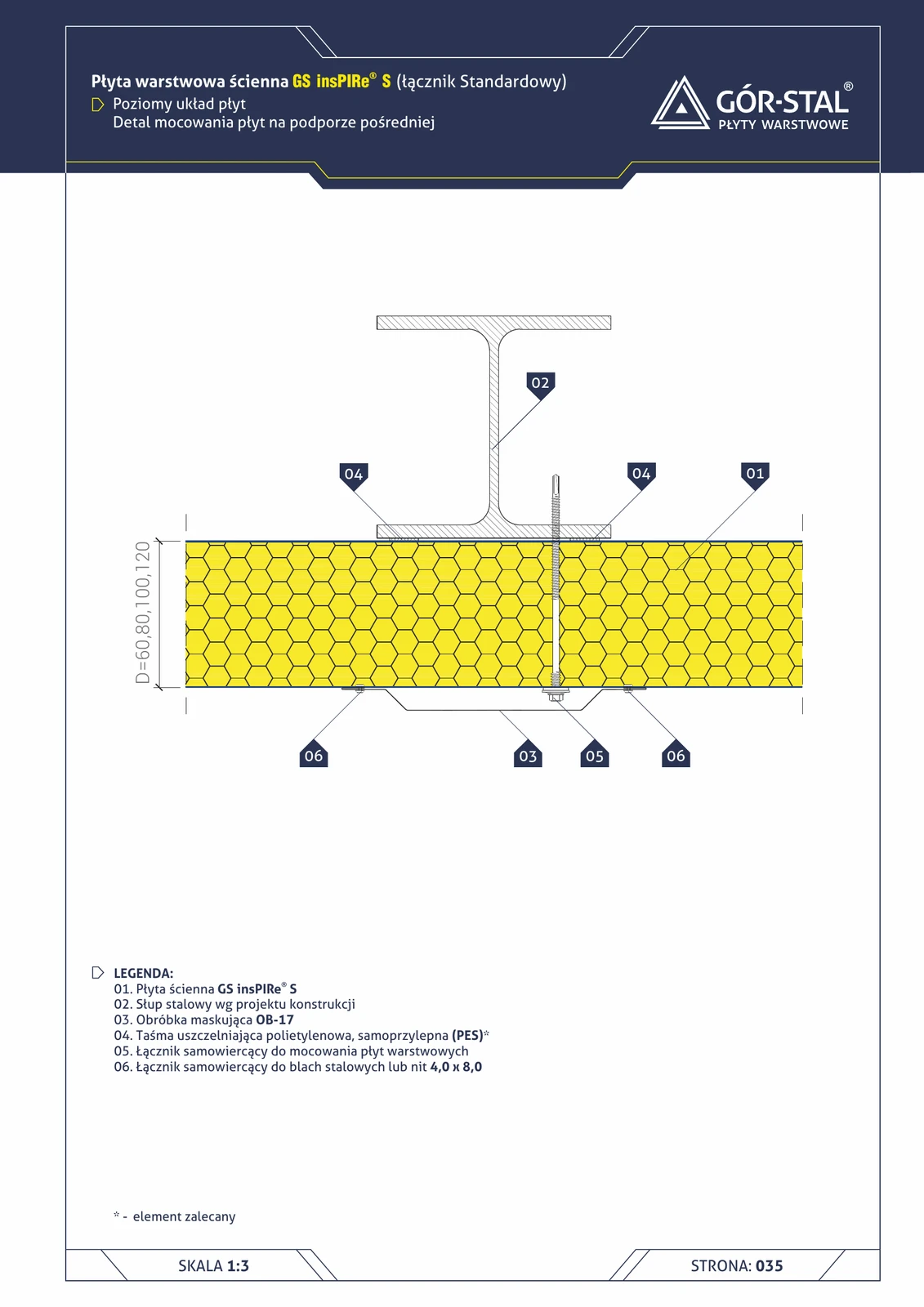
End support — horizontal insPIRe® S panel layout
Fixing horizontally laid PIR panels to the end support (end column of the hall). Concealing OB-17 flashing + installation foam in the space adjacent to the column.

Balcony in ETICS termPIR® ETX — vertical section
The most challenging detail in a single-family house: a reinforced concrete balcony projecting from an ETICS-insulated wall. The balcony slab is a linear thermal bridge ψ ≈ 0.8 W/m·K — elimination: balcony soffit insulation with ETX + a layer of termPIR® WS beneath the balcony floor.
ETICS termPIR® ETX — Typical Wall Section
Classic two-layer external wall insulation with the termPIR® ETX system (PIR ETICS board with ETA 17/0066). Bonding + mechanical fixing + mineral render on mesh. Class B-s1, d0 — fire safety of a system with mineral cover.
Structural expansion joint — horizontal GS MW S/CH panel layout
Detail of a structural expansion joint in a hall with horizontal panel layout — analogous to the vertical layout (p. 24). Custom flashing absorbing ±20 mm of structural movement, OB-17 cover trim, mineral wool insulation installed on site.
Structural expansion joint — horizontal insPIRe® S panel layout
Building structural expansion joint detail in a hall with horizontal PIR panels. Custom expansion flashing absorbing ±20 mm movement, OB-17 cover flashing, thermal insulation installed on site.
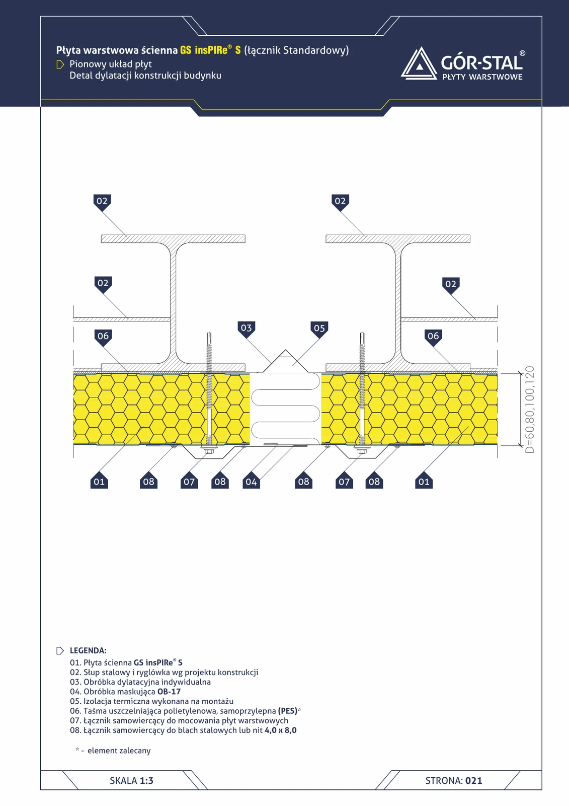
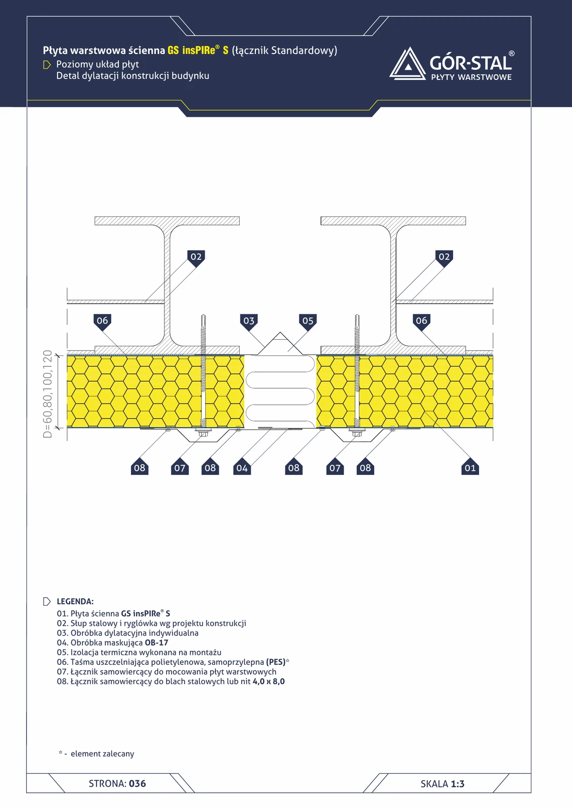
Structural Expansion Joint — Vertical insPIRe® S Panel Layout
Detail of a building structural expansion joint in a hall with vertical PIR panels. Custom expansion flashing absorbing ±20 mm of movement, OB-17 cover flashing, thermal insulation installed on site.
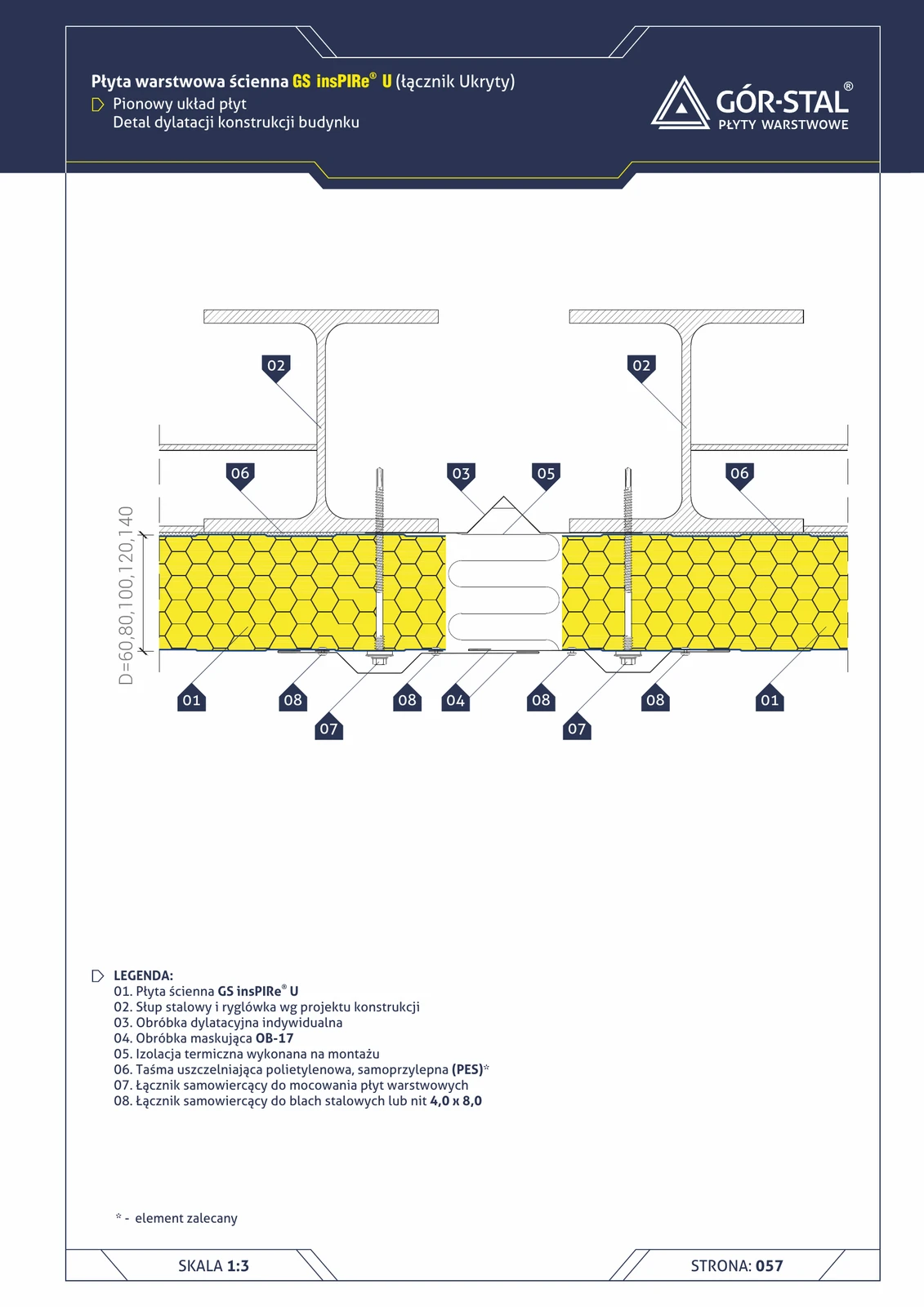
Structural expansion joint — vertical insPIRe® U panel layout
Expansion joint detail for halls with premium vertical PIR panels. Custom ±20 mm expansion flashing, OB-17 cover trim, on-site insulation.
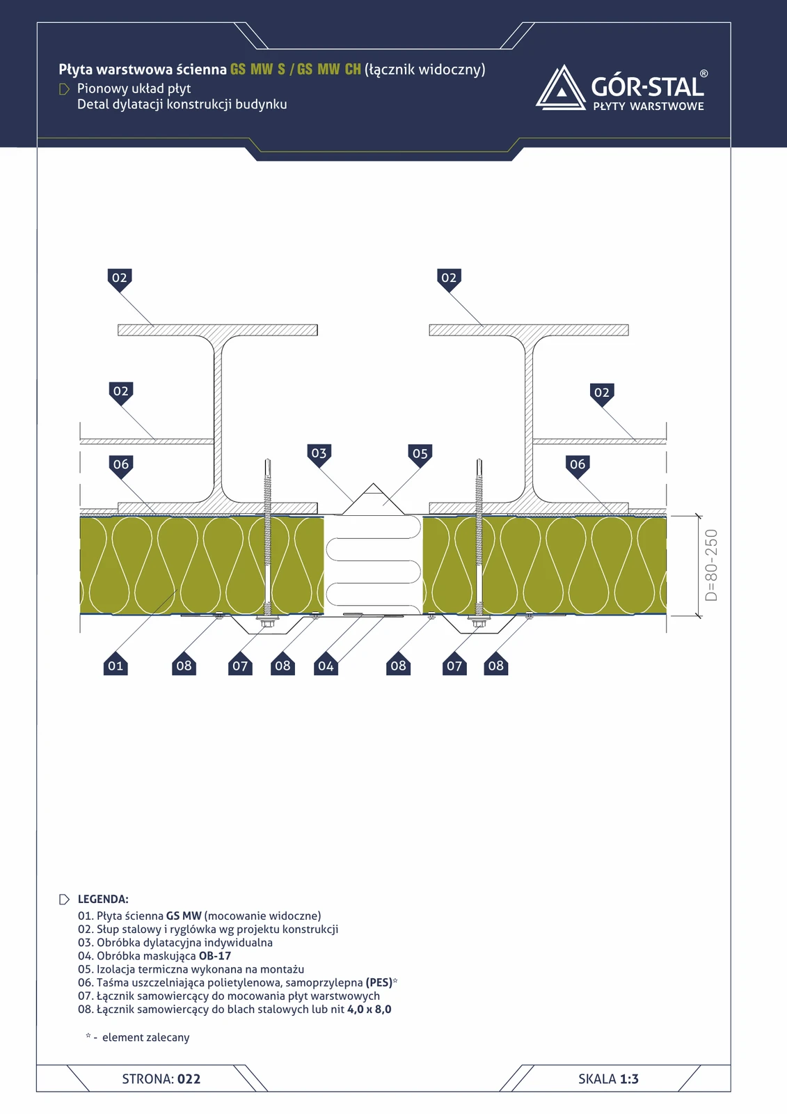
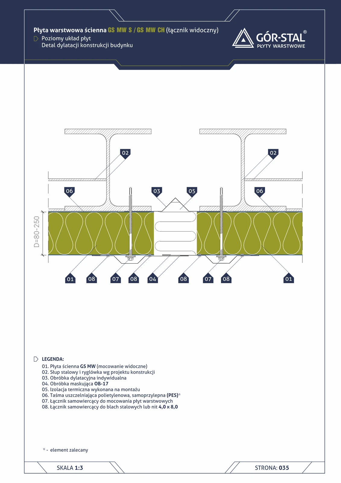
Structural expansion joint — vertical GS MW S/CH panel layout
Detail of building structural expansion joint in a hall with vertical panel layout. The structural joint (horizontal steel frame movement up to ±20 mm) requires a flexible expansion flashing + OB-17 cover flashing, with thermal insulation installed on site.
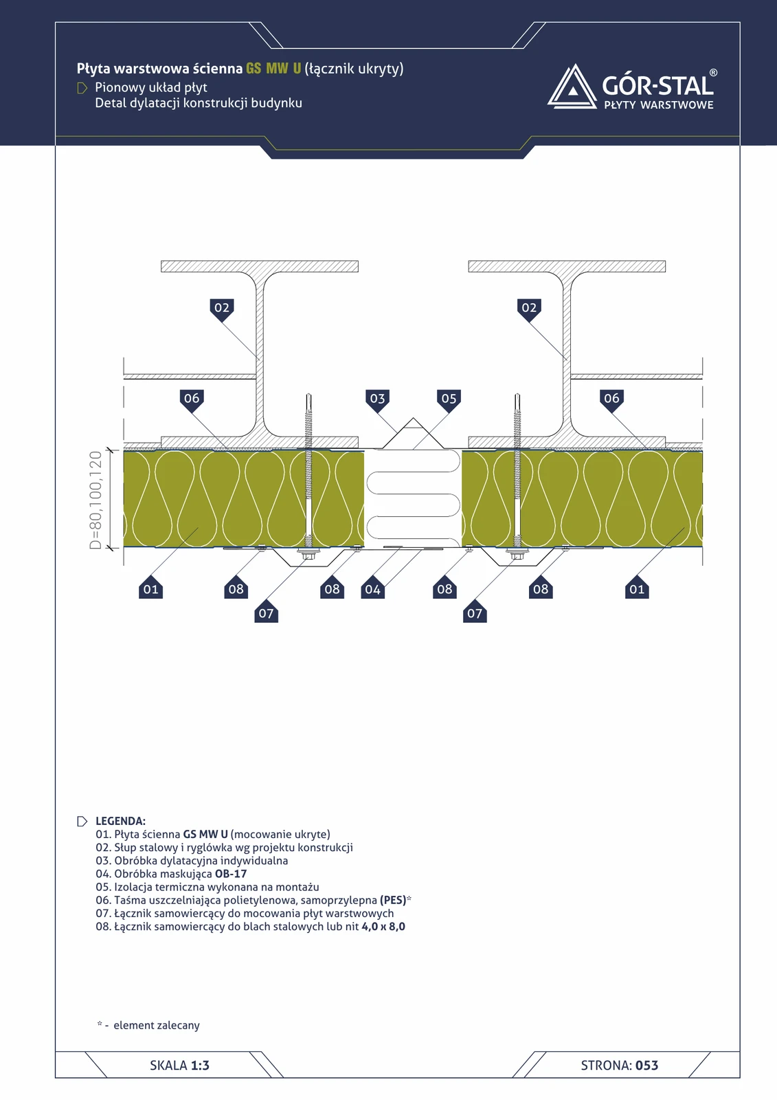
Structural expansion joint — vertical GS MW U panel layout
Building structural expansion joint in a hall with vertical GS MW U panels. Identical logic as in S/CH (page 24) — custom expansion flashing absorbing ±20 mm movement, OB-17 cover flashing, mineral wool loosely packed.
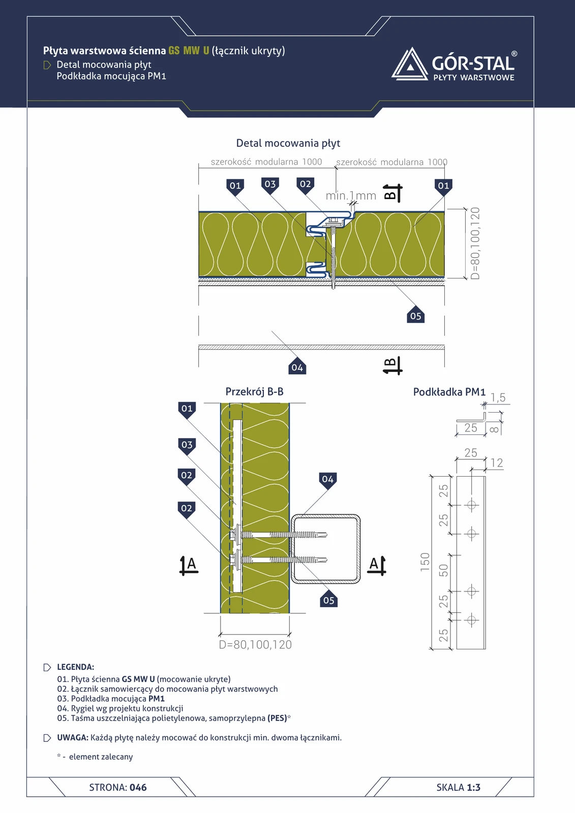
GS MW U Panel Fastening — PM1 Washer
Cross-section of GS MW U panel fastening with concealed fastener using PM1 mounting washer. Self-drilling fastener hidden in the joint — zero visible heads on the façade. Each panel must be fixed with a minimum of two fasteners.
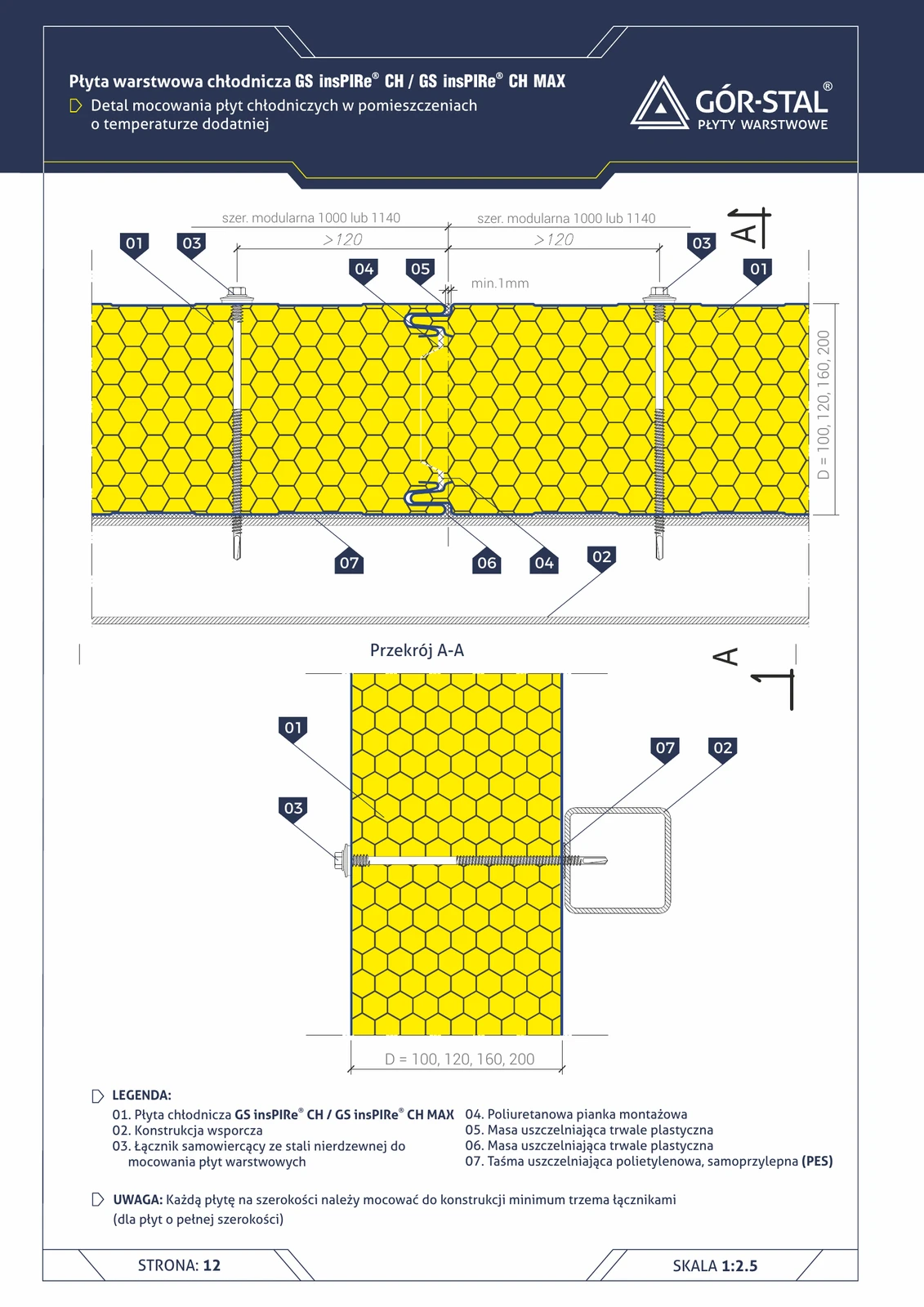
Fixing of insPIRe® CH panels — positive temperature (t > 0°C)
Horizontal + cross-section (A-A) of cold storage panel fixing in rooms with temperatures above 0°C (fruit, vegetable, dairy cold rooms). Stainless steel self-drilling fasteners + installation foam + plastic sealant.
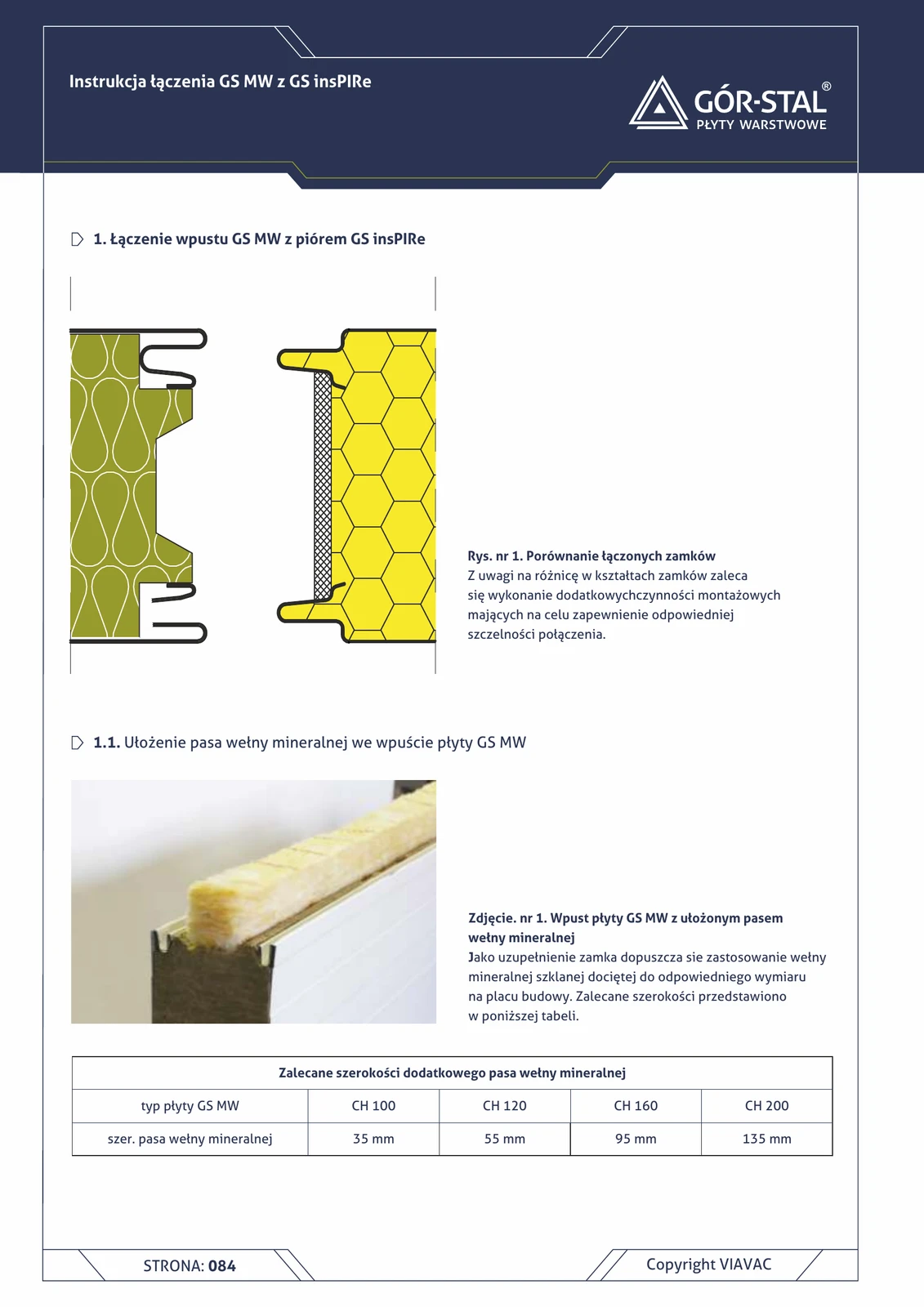
GS MW × GS insPIRe joint — groove on insPIRe side, tongue on MW side
The second of two possible MW × insPIRe joint configurations (depending on panel installation orientation). The grooved edge of the insPIRe panel meets the tongued edge of the MW panel. The MW tongue is **too large for the insPIRe groove** — it must be **cut out with a router** and sealed with a gl
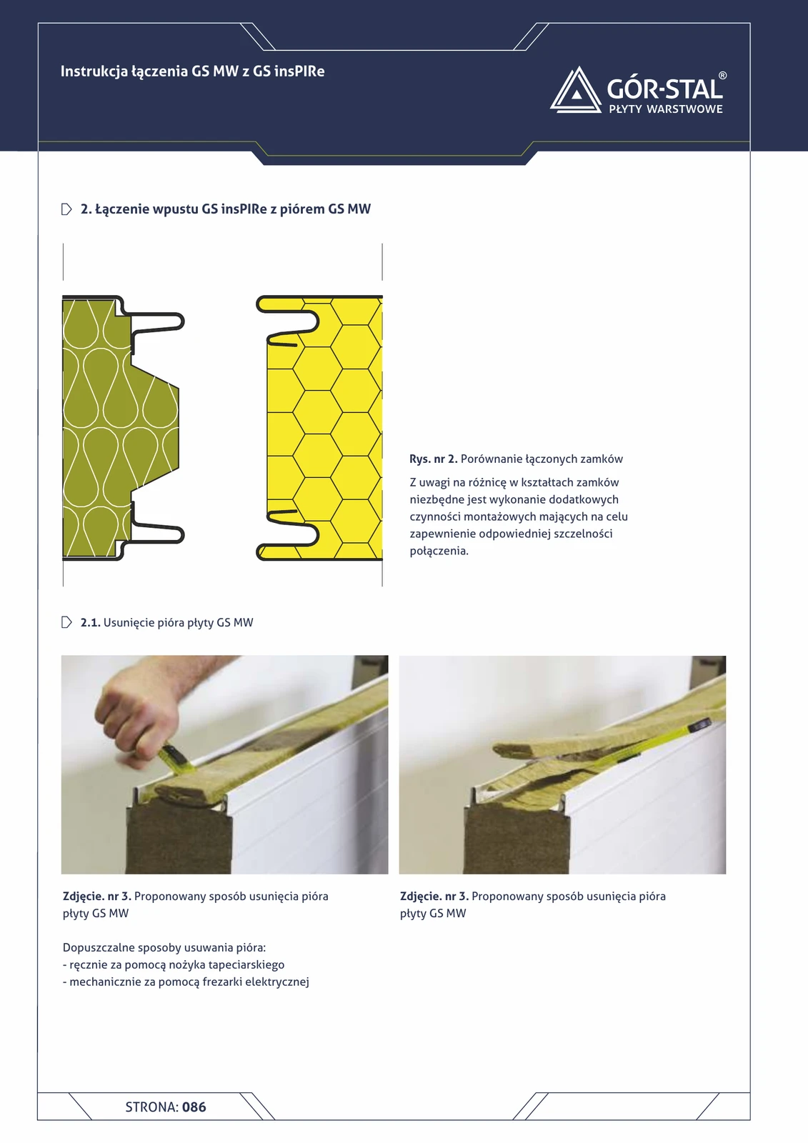
GS insPIRe (groove) + GS MW (tongue) joint
Reverse variant of the mixed joint: GS insPIRe groove + GS MW tongue. Requires **removal of the MW tongue** with a utility knife or router, and sanding of the edges for proper fit.

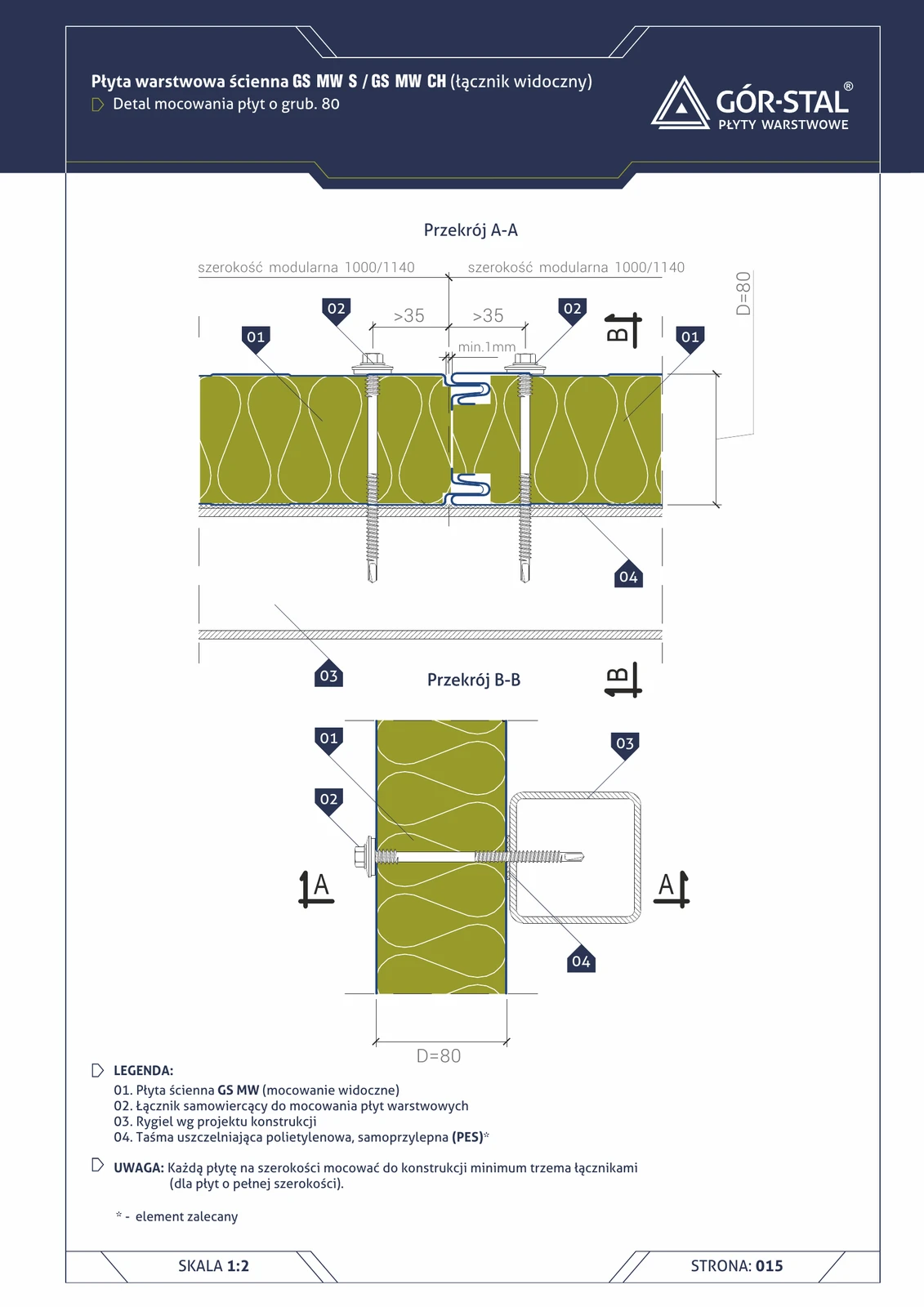
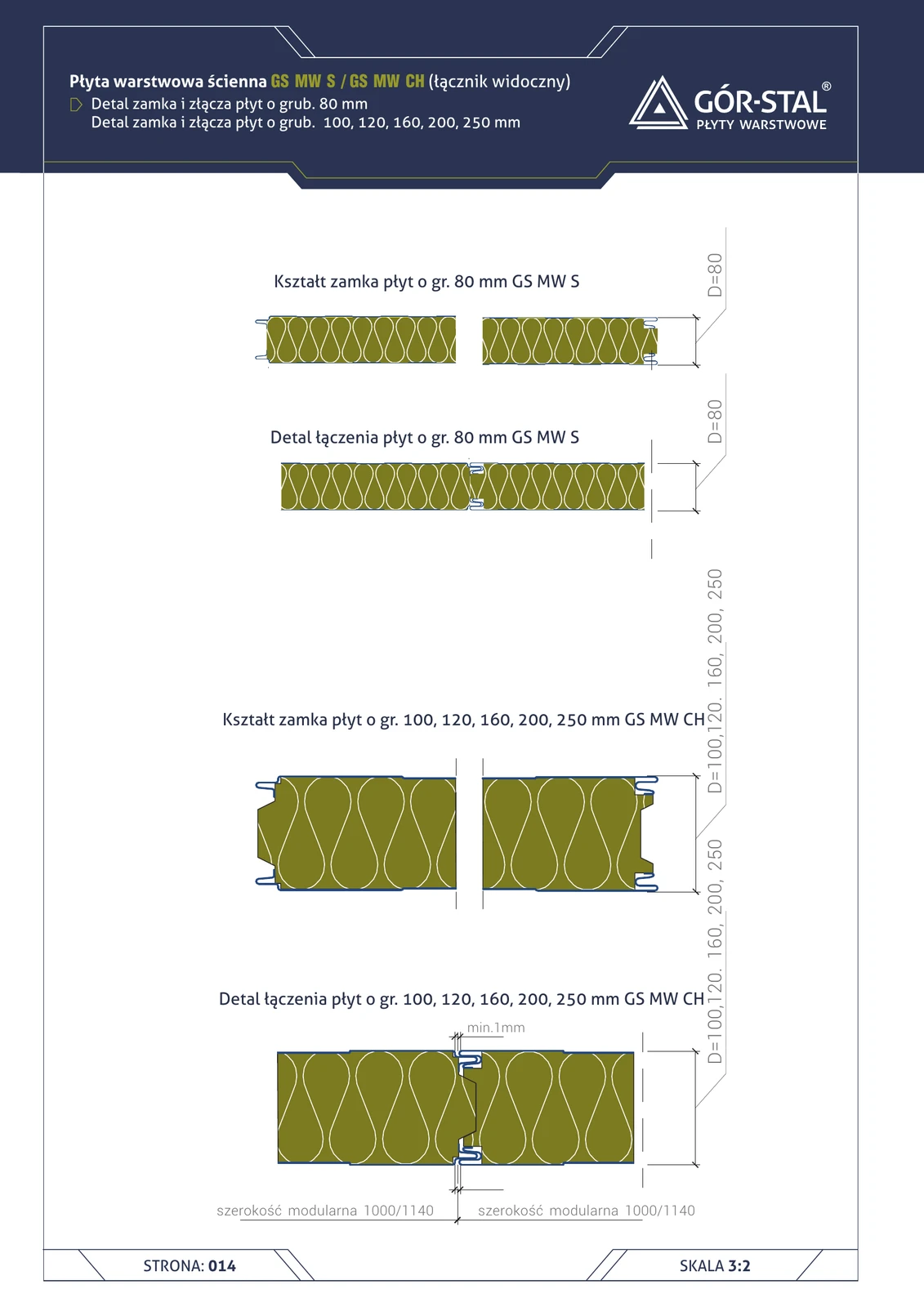
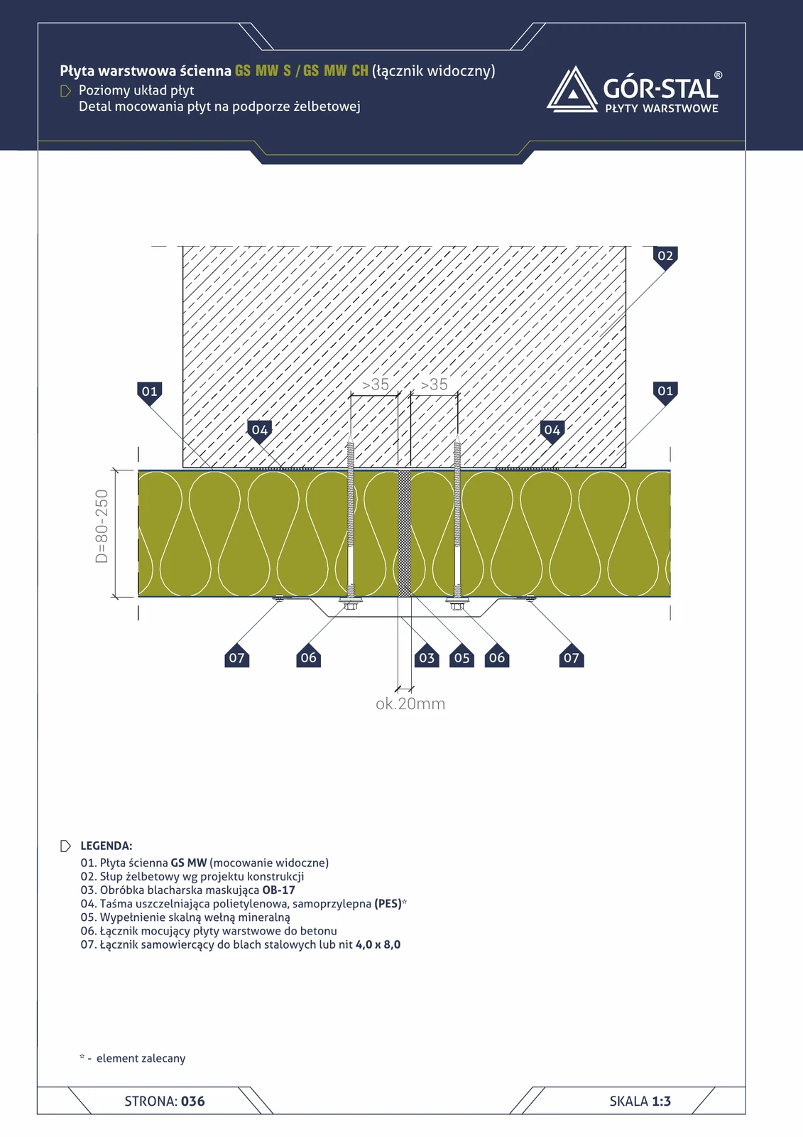
GS MW S 80 mm lock + panel joint
Cross-section of the side lock of a standard GS MW S sandwich panel (mineral wool) 80 mm thick. Tongue-and-groove geometry provides joint tightness at a modular width of 1000/1140 mm. Fastener visible in the lock.
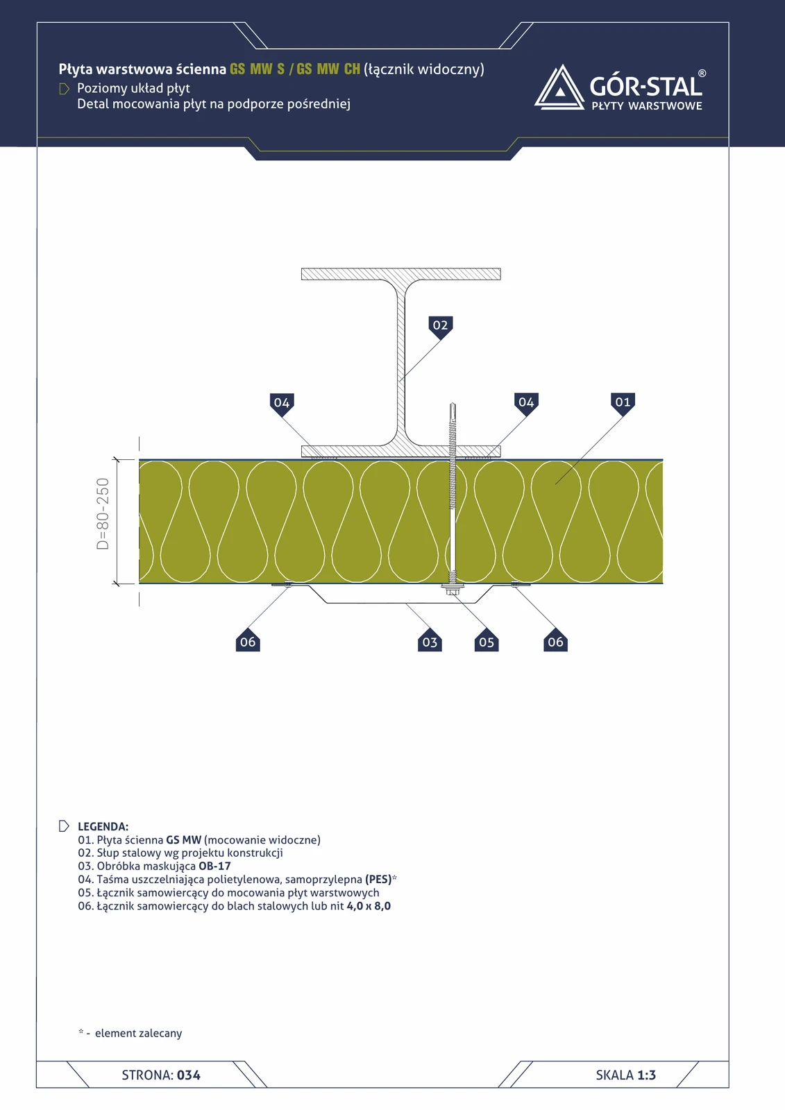
Fastening of GS MW S/CH panels, 80 mm thick, to purlin
A-A and B-B cross-section showing the method of fastening the GS MW S/CH sandwich panel to a steel purlin using self-drilling fasteners. Minimum 3 fasteners across the panel width. PES sealing tape between the panel and the purlin.
Historic wall AL GK — framing installation (vertical section)
Internal insulation variant using timber or steel framing — for historic walls that are uneven, distorted, or locally unstable (e.g. detaching plaster). Framing similar to a typical plasterboard wall, but thicker to accommodate the insulation layer AL GK.
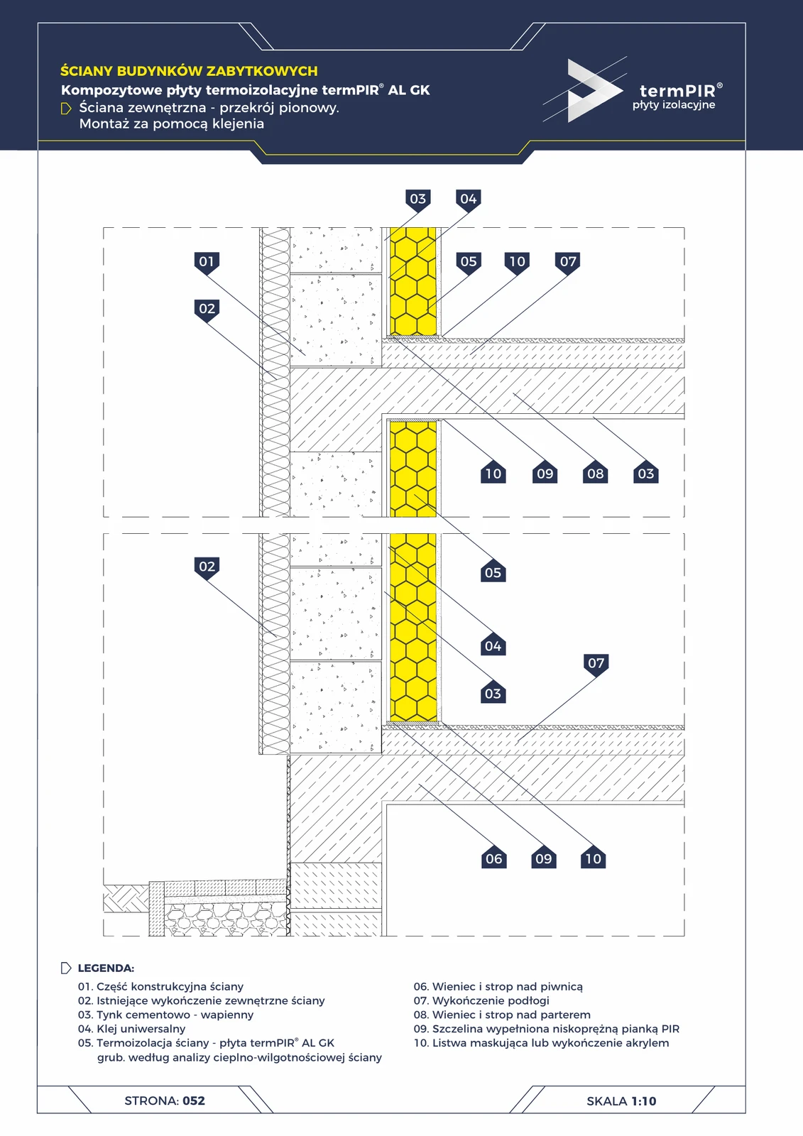
Historic wall AL GK — glued installation (vertical section)
Wall insulation in heritage buildings where the façade cannot be modified (tenement houses, manors, monasteries). termPIR® AL GK board glued full-surface from the inside — simultaneously PIR insulation + factory plasterboard as finish. No framing → minimal loss of living space.
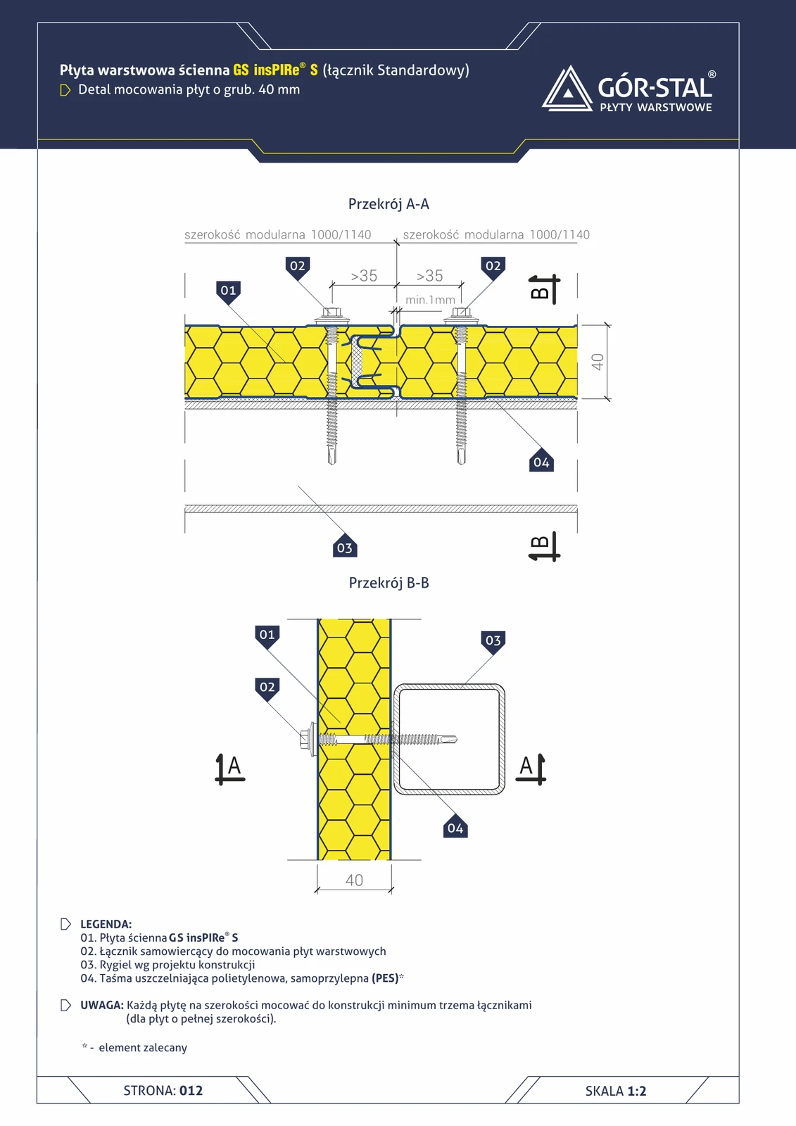
insPIRe® S 40 mm panel fastening — section A-A and B-B
Point fastening of the thinnest insPIRe® S panel to a steel purlin using self-drilling fasteners. Minimum 3 fasteners across the 1000 mm panel width. PES sealing tape between panel and purlin.
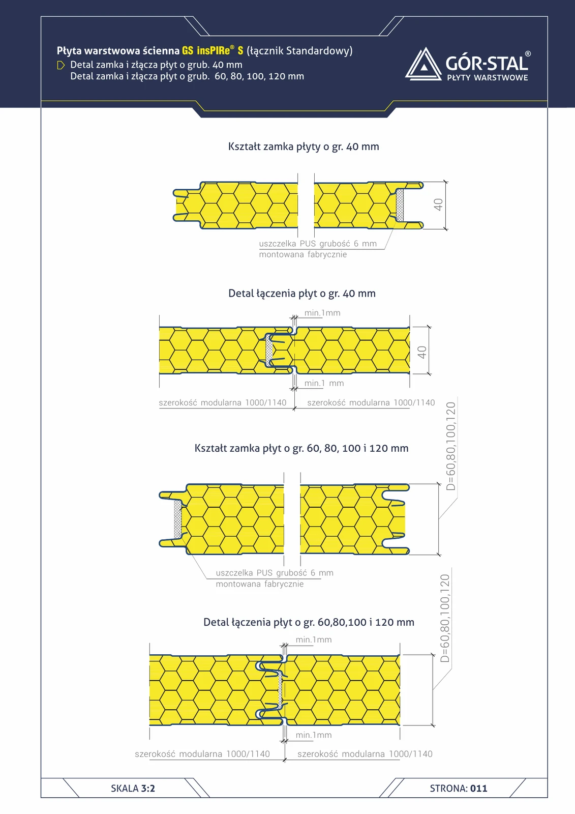
insPIRe® S 40 mm panel lock + joint
Cross-section of the side lock of the thinnest PIR sandwich panel — GS insPIRe® S 40 mm. The 6 mm PUS gasket factory-fitted in the lock ensures class 1 tightness per PN-EN 14509. Modular width 1000 / 1100 mm.

insPIRe® S panel lock + joint 60-120 mm
Side lock cross-section of standard insPIRe® S PIR sandwich panels 60, 80, 100 or 120 mm. Identical lock geometry regardless of thickness — the same 1000 mm module for all thicknesses.
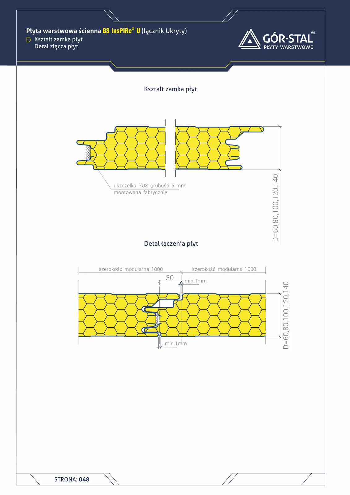
insPIRe® U panel lock + joint (concealed fixing)
Cross-section of the hidden lock of the GS insPIRe® U PIR sandwich panel. Fastener concealed inside the lock, invisible on the facade — the cleanest aesthetic available in sandwich panel technology. Modular width 1000 mm.
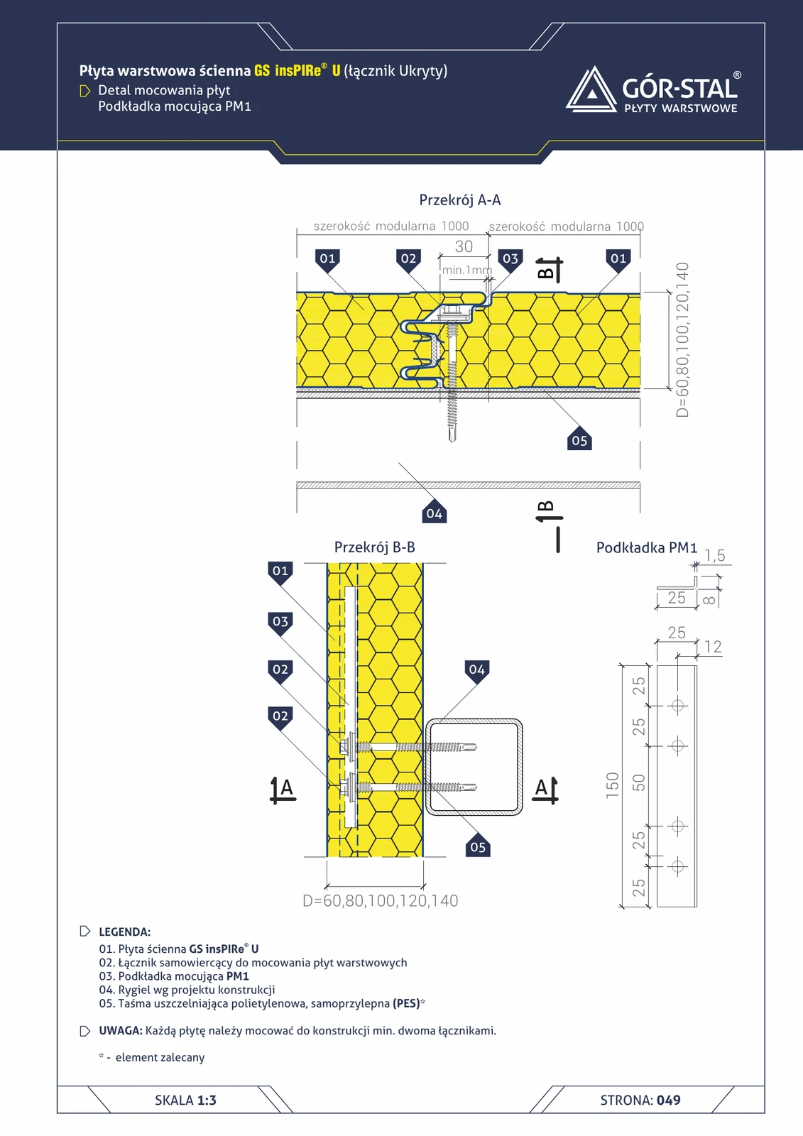
insPIRe® U panel fastening — PM1 washer
Cross-section of the insPIRe® U panel fastening junction with concealed fastener via PM1 washer. Self-drilling fastener hidden in the joint — zero visible heads on the façade. Min. 2 fasteners per panel.
Intermediate support — horizontal arrangement of GS MW S/CH panels
Fixing horizontal panels at an intermediate support — a structural column between two consecutive bays of the hall. The panel continues through the column (it does not terminate as at an end support). OB-17 flashing covers the joint with the column from outside.
Intermediate support — horizontal layout of GS MW U panels
Premium fastening of horizontal panels at the intermediate support of an industrial hall. The panel continues across the column (continuous junction), PM1 fasteners are concealed in the joint — no external cover flashing required. The cleanest premium facade aesthetic.
Intermediate support — horizontal insPIRe® U panel layout
Premium fastening of horizontal panels on an intermediate support. Continuous junction, PM1 within the joint — no external trim required. Cleanest aesthetics.
Intermediate support — horizontal insPIRe® S panel layout
Fixing horizontal PIR panels at an intermediate support. The panel runs continuously past the column (through-junction); OB-17 trim flashing conceals the joint with the column on the outer face.
Joint GS MW × GS insPIRe — MW groove on MW side, insPIRe tongue on insPIRe side
Every sandwich panel has a tongue on one edge and a groove on the other (tongue-and-groove lock). This detail shows a **specific joint orientation** at the boundary between MW and insPIRe zones: the groove edge of the MW panel meets the tongue edge of the insPIRe panel. The insPIRe tongue is smalle
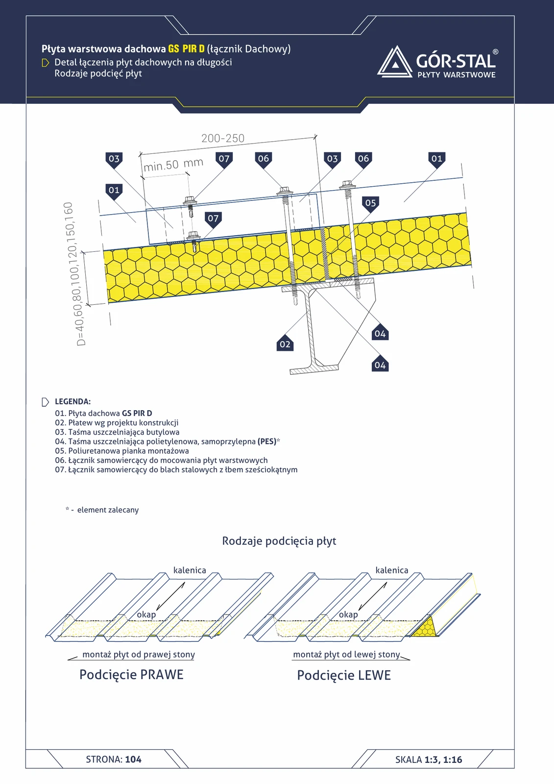
Lengthwise joint of D roof panels — types of undercuts
Detail of joining GS PIR D roof panels **along their length** at the purlin — when the roof length exceeds the length of a single panel. 200-250 mm overlap, butyl sealing + assembly foam. Shows two types of factory undercuts.
GS MW CH Panel Lock + Joint 100–250 mm
Cross-section of the side lock of the GS MW CH sandwich panel (mineral wool, cold storage) for the full thickness range 100/120/160/200/250 mm. Identical lock geometry regardless of thickness — simplifies logistics and installation of mixed facades.
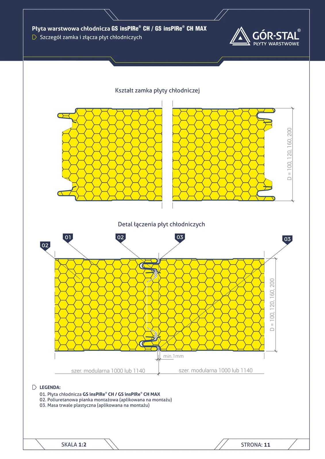
Lock + joint of insPIRe® CH panels (cold storage)
Cross-section of GS insPIRe® CH / CH MAX cold storage panel lock. Vs S lock — the cold storage version has additional **assembly foam + permanently plastic sealant** in the joint for absolute vapour tightness (50-60°C temperature differential between cold room and corridor).
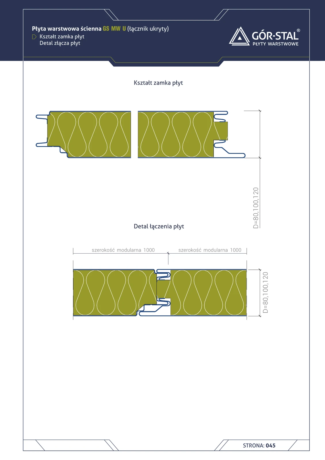
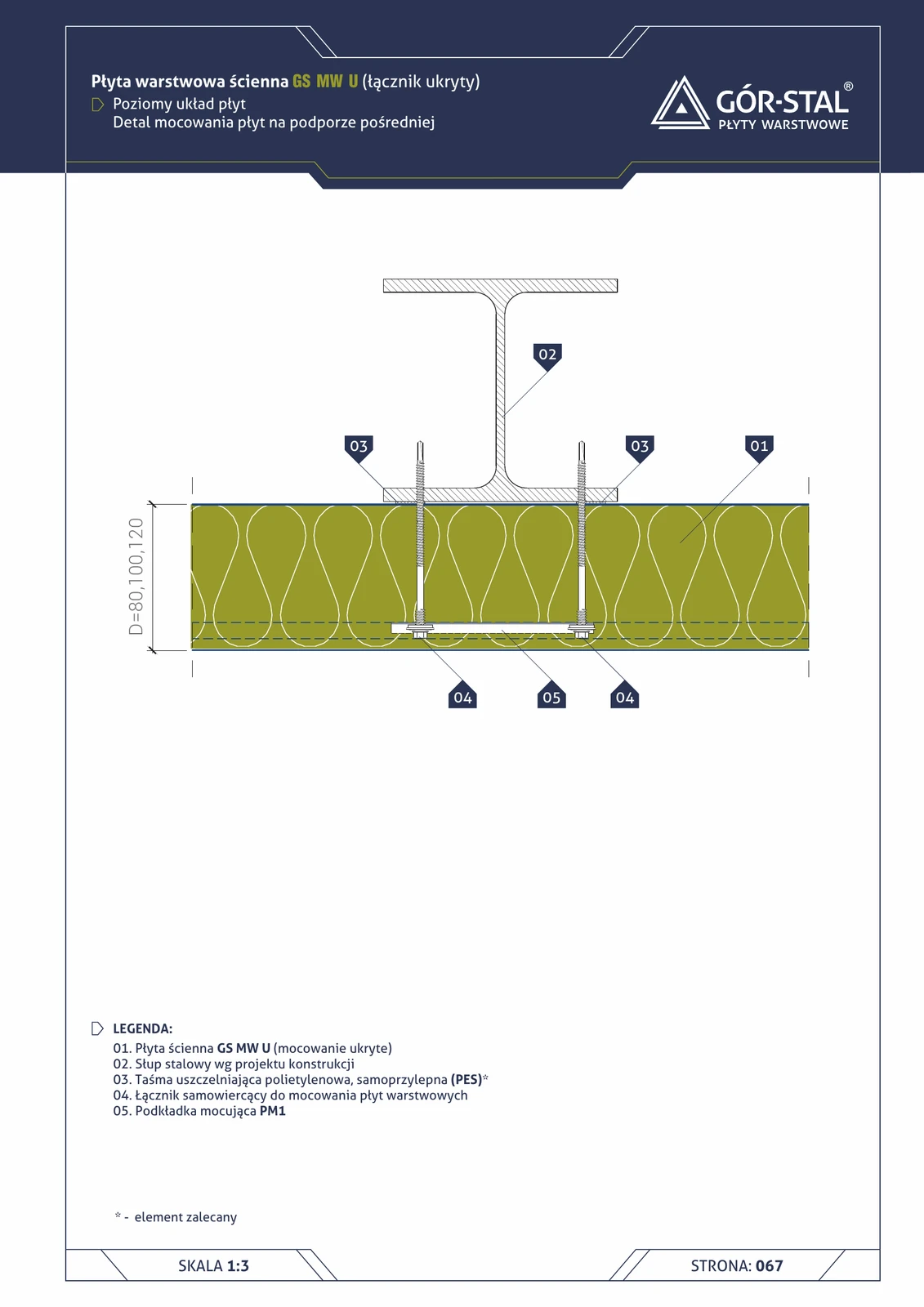
GS MW U panel lock + joint (concealed fastening)
Cross-section of the concealed lock of GS MW U sandwich panel (mineral wool, premium fastening). Fastener hidden inside the lock geometry, invisible on the facade — the cleanest aesthetics available in mineral wool sandwich panel technology. Modular width 1000 mm.
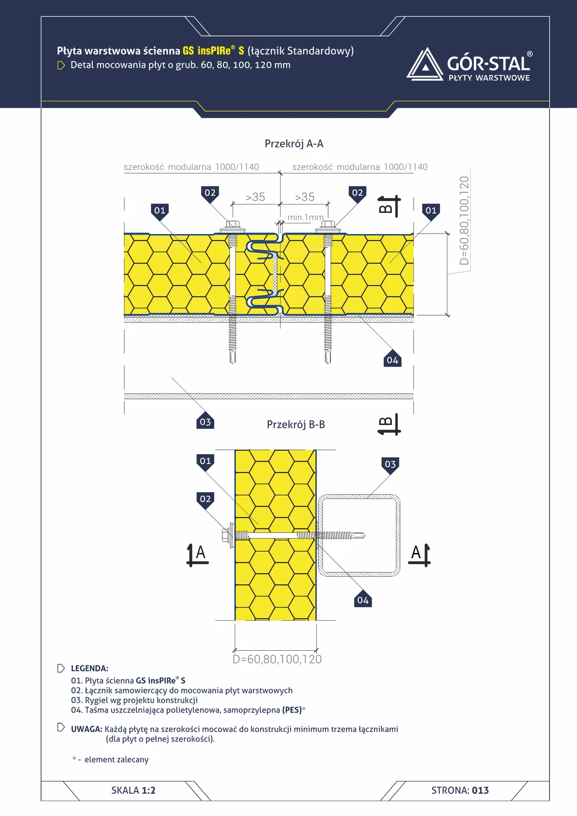
Fixing of insPIRe® S panels 60-120 mm thick — section A-A and B-B
Standard fixing of insPIRe® S sandwich panels 60-120 mm thick to steel purlin. Self-drilling fasteners in the centre of the joint, minimum 3 pieces per 1000 mm width. PES sealing tape at panel-purlin interface.
Mounting of insPIRe® CH panels — negative temperature (t < 0°C)
Horizontal section + A-A of freezer panel mounting to the supporting structure in rooms with temperatures below 0°C. **Thermal insulating PVC fastener system + Ø10 threaded rod** instead of standard steel fasteners — eliminates the thermal bridge critical in freezer rooms.

Partition wall at ceiling
Top fixing of a light partition wall to the ceiling. UW profile with slip tape — allows ceiling deflection under load (typically 1–3 mm/m) without cracking the partition wall. Critical on the ground floor below a residential storey.
Partition wall at floor
Bottom fixing of a lightweight partition wall. UW profile (horizontal) anchored to the floor with acoustic sealing tape. Perimeter expansion gap allows for thermal movement. Floor finish bypasses the UW profile (tiles, panels, parquet).
RC support — horizontal GS MW U panel layout
Premium fastening of horizontal panels to RC column. Chemical or mechanical anchors for concrete, PM1 for U-joint geometry, OB-17 cover flashing, mineral wool in 20 mm gap.
RC support — horizontal layout of GS MW S/CH panels
Fixing horizontal panels to a reinforced concrete column (instead of the typical steel one). Special concrete anchors replace standard self-drilling fasteners — higher load capacity but slower installation. Used in halls with mixed structural systems.
RC column support — horizontal insPIRe® S panel layout
Fixing horizontal PIR panels to a reinforced concrete column (instead of a typical steel one). Special chemical anchors for concrete, OB-17 cover flashing, foam sealant in a 20 mm gap.
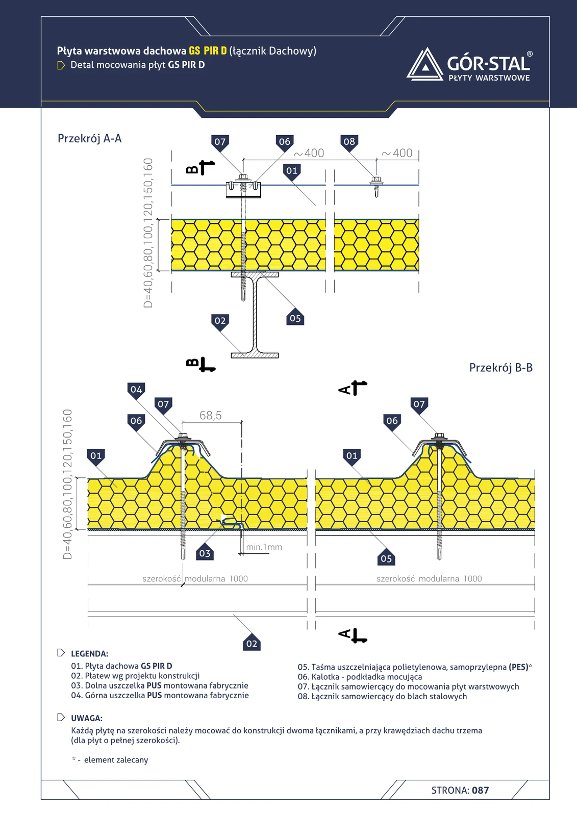
GS PIR D roof panel fastening to purlins
Self-drilling fasteners with cap washers secure roof panels to the steel purlin. Min. 2 fasteners per panel, 3+ in the edge zone. Upper + lower PUS gaskets factory-fitted, PES tape.

GS PIR D panel lock + joint
Cross-section of the GS PIR D roof panel lock with trapezoidal external profile. 6 mm thick PUS gasket factory-fitted in the lower part of the lock. Thicknesses 40-160 mm.
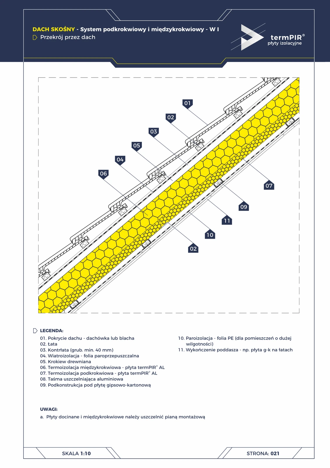
Pitched roof — under-rafter + between-rafter W1 system (section)
Variant I of a roof with insulation in two layers: the first between rafters (item 06), the second suspended under the rafters (item 07). Eliminates the thermal bridge at the rafters + does not require removing the existing roof covering. The most popular system for thermal upgrading.
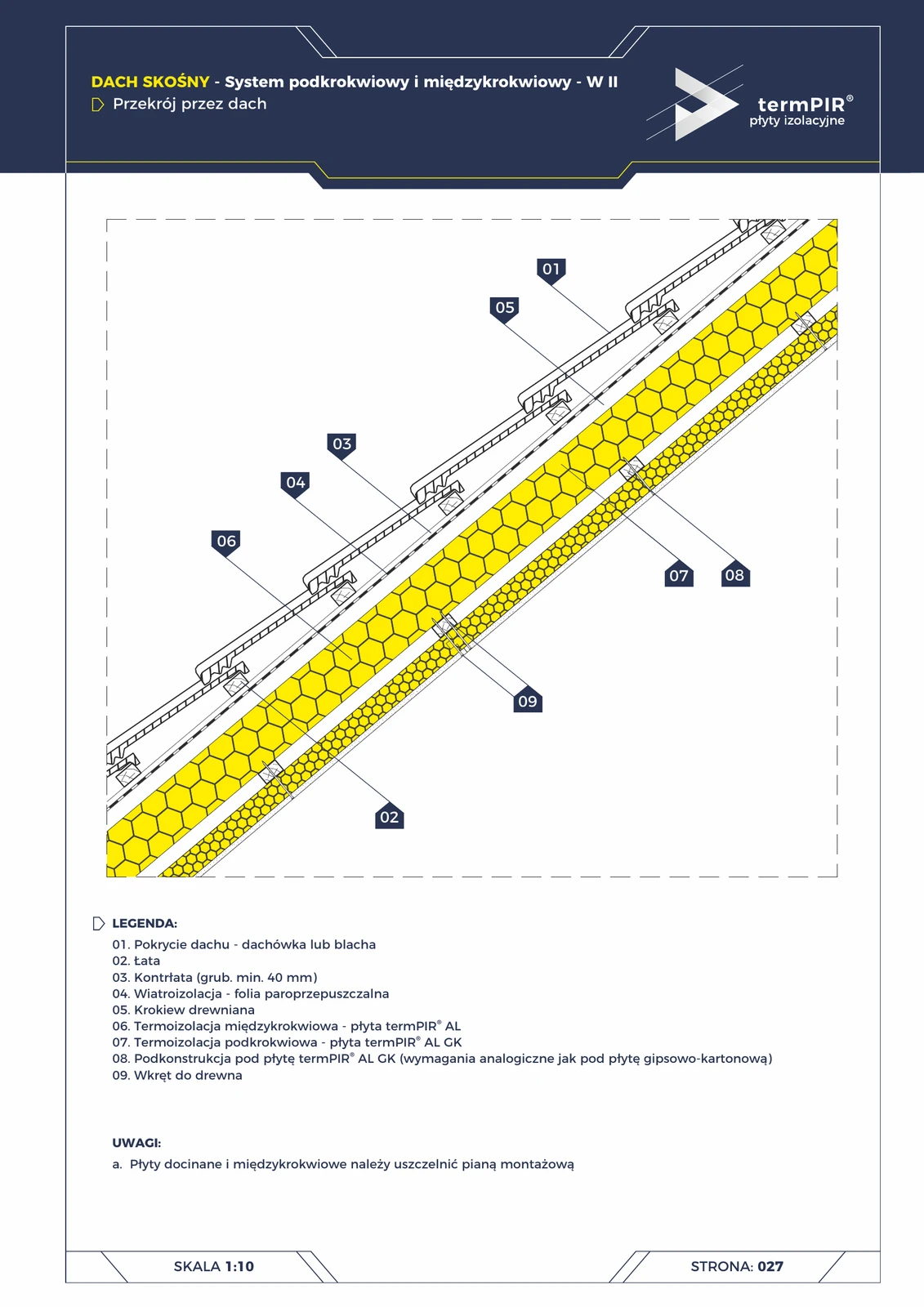
Pitched roof — under-rafter + between-rafter system W2 (section)
Variant II: termPIR® AL between rafters + termPIR® AL GK (composite panel with factory-laminated plasterboard) as the under-rafter finish. Eliminates the separate plasterboard layer → faster installation, reduced storey thickness.
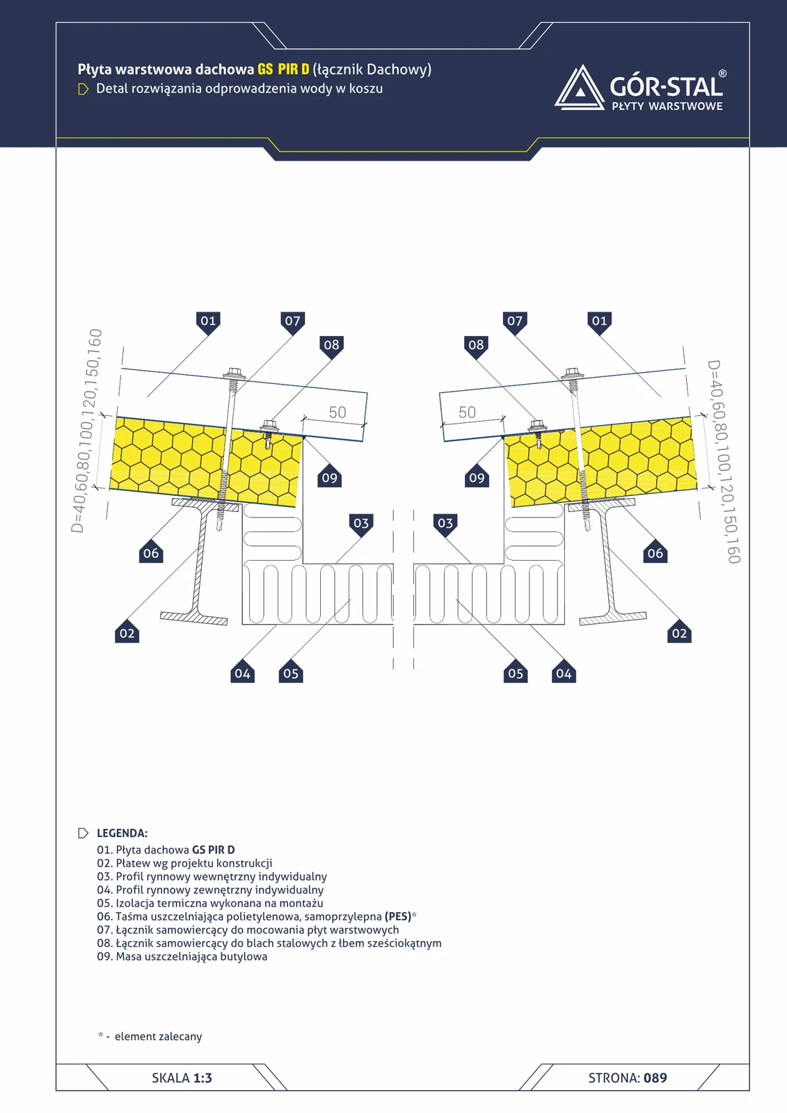
Roof valley — water drainage (GS PIR D)
Valley zone detail in gable roof — where two roof slopes meet at an acute angle (inside of the roof). Internal + external gutter profiles collect water and discharge it to the eaves gutter. 50 mm gap between panels on both sides.
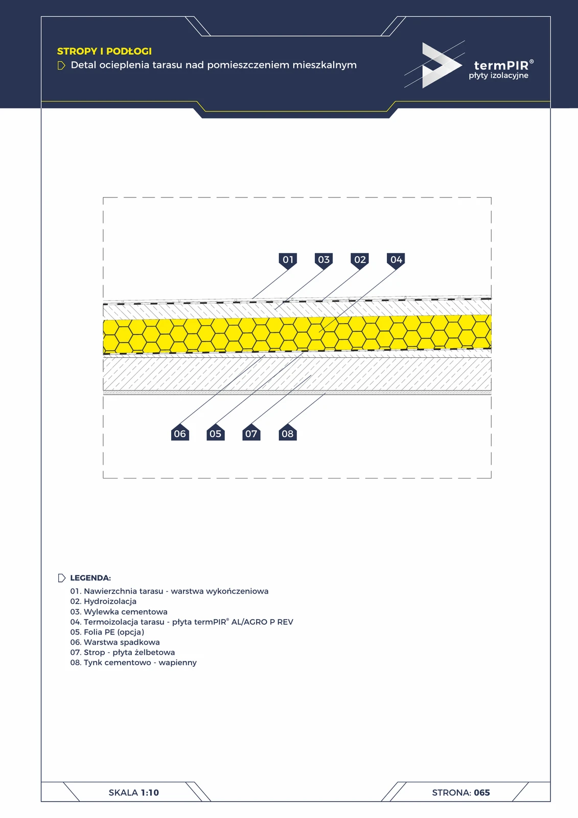
Terrace over living space (termPIR® AL)
A terrace on a slab over heated space requires simultaneous waterproofing + thermal insulation + slope. A termPIR® AL board under the waterproofing layer eliminates the thermal bridge through the slab. A 1.5% slope layer drains water beyond the building footprint.
Three-layer basement wall (termPIR® AL in cavity + floor)
Full 3-layer construction from footing to roof: load-bearing leaf + termPIR® AL + clinker facing leaf. Basement floor insulated with termPIR® AL. The most durable basement construction.
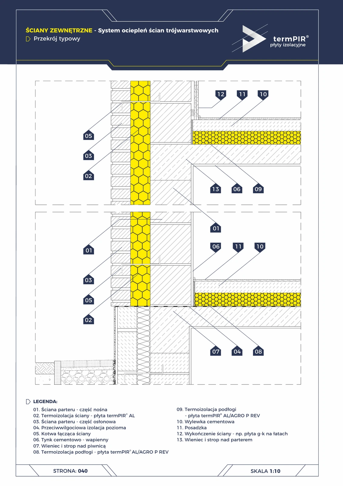
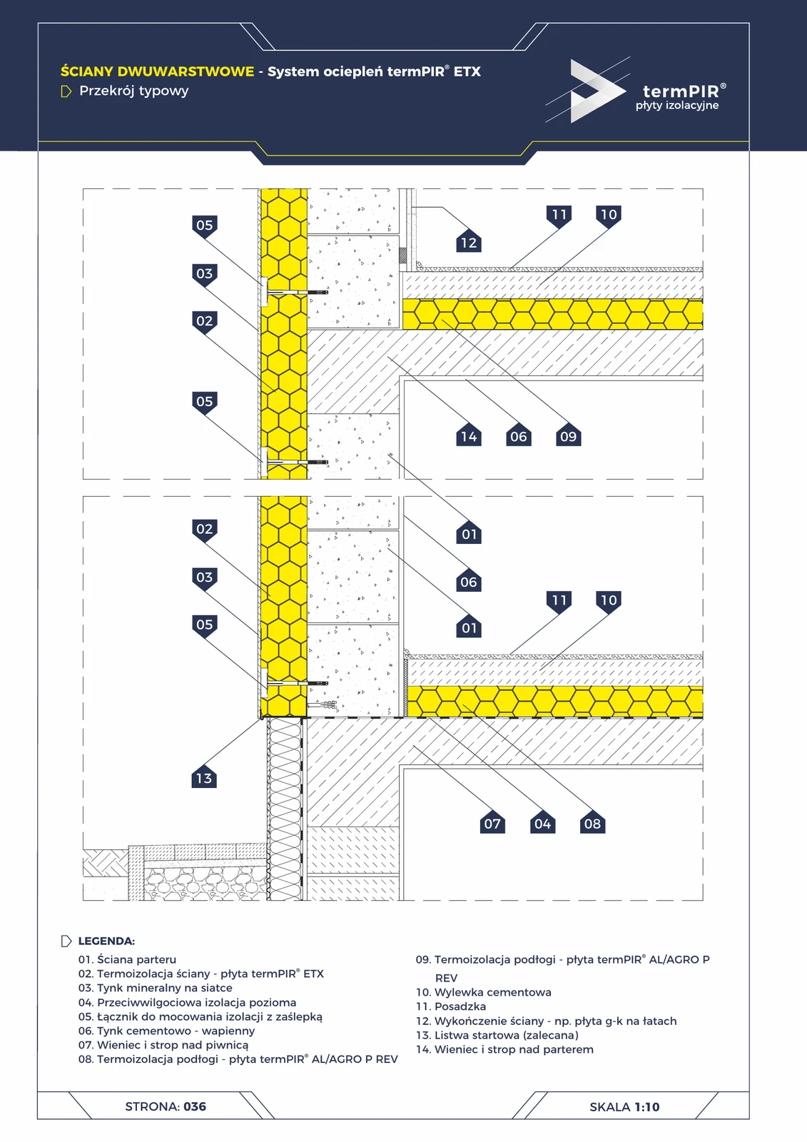
Three-layer wall with termPIR® AL — typical section
Classic three-layer wall structure: load-bearing leaf (brick / block) + termPIR® AL insulation + outer leaf (clinker brick, silicate, aerated concrete). Connected with steel ties. The most durable external wall — facade requires no painting.
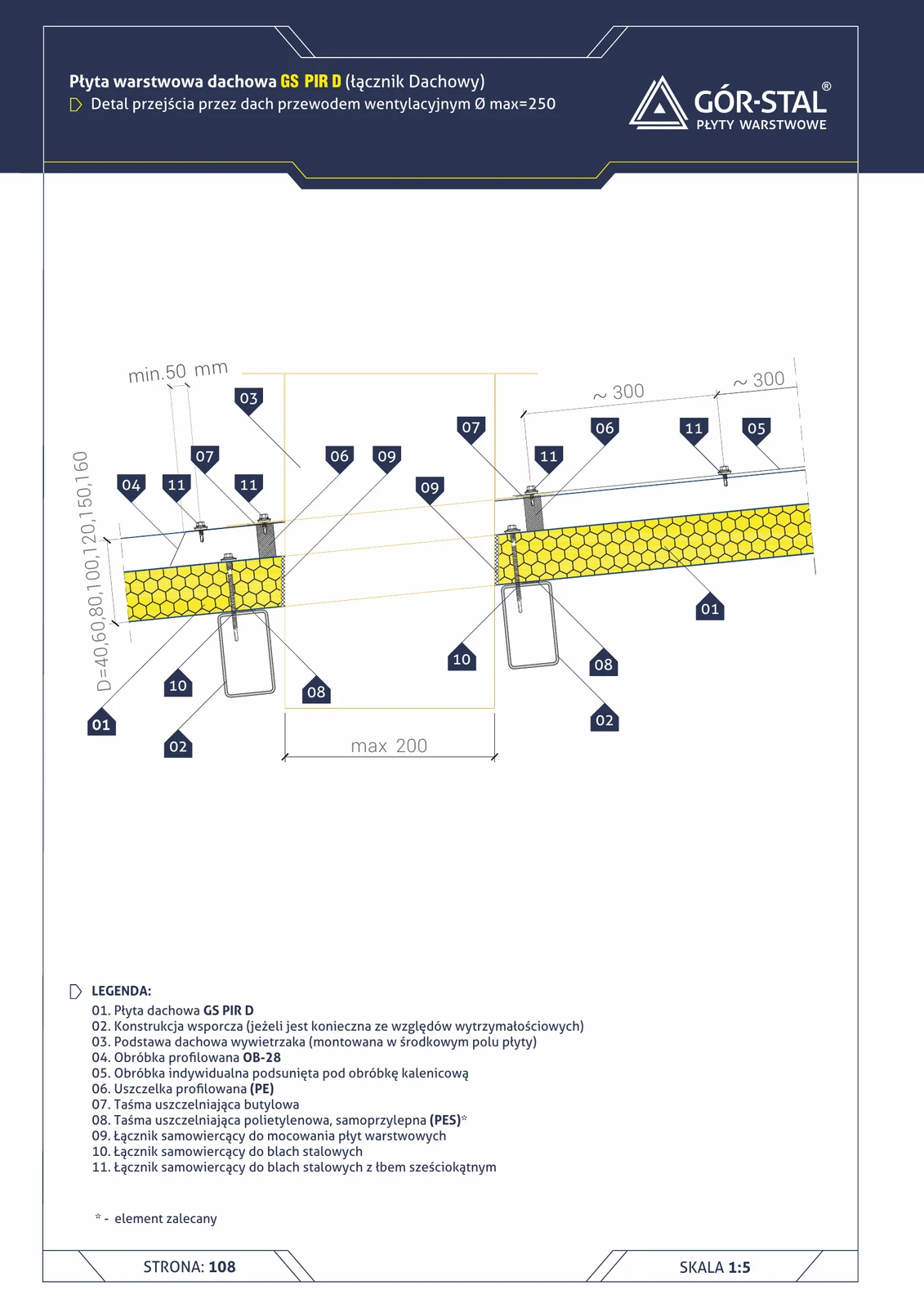
Ventilation duct — roof penetration (GS PIR D)
Penetration detail for a ventilation duct (vent stack, roof cowl, HVAC duct) through the roof panel. Vent base located in the central field of the panel, min. 300 mm from the edge. Custom flashing tucked under the ridge flashing.