Junction function
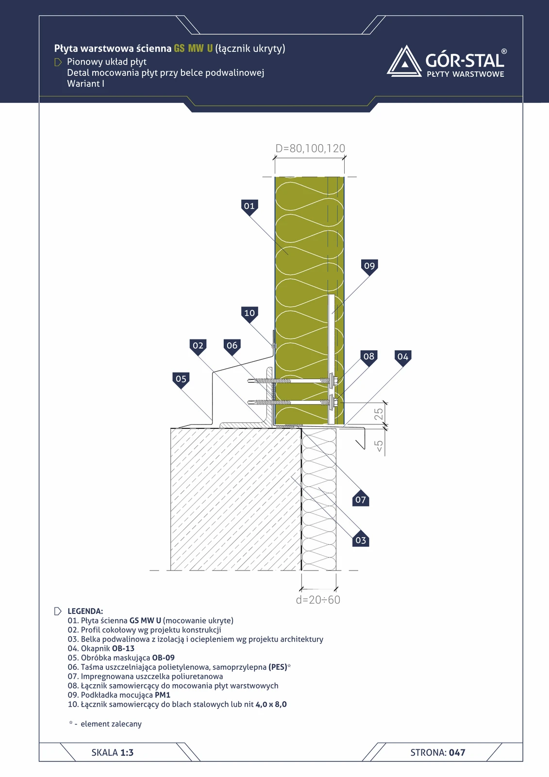
GS MW U plinth with concealed fixing = premium variant of the vertical plinth. Vs S/CH (p. 16):
- Invisible fastener — hidden inside the joint via PM1 washer.
- OB-09 cover flashing instead of typical OB-08 — geometric difference for U-joint geometry.
- Premium aesthetics — no fastener head visible on the lower façade.
Variant I = projection d=20-60 mm, visually discreet drip edge. Used in car showrooms, offices adjacent to halls, eco-buildings.
Critical installation aspects
- PM1 washer (item 09) — key element of the concealed fixing system; fastened with a screw through the panel joint into the sill beam.
- OB-09 cover flashing — wider than OB-08 (for U-joint geometry); covers the joint of the panel’s lower edge.
- Remaining rules = as in S/CH variant (p. 16): installation foam under the panel, contact with the beam, 30 mm drip on OB-13.
Documentation
Technical Catalogue GS MW S/CH/U (Gór-Stal 2025), page 45 — Plinth, vertical GS MW U layout, variant I. Scale 1:5.
Components in this junction
Panel (1)
- 01
Flashing (3)
- 02 Plinth profile per structural design
- 04 OB-13 drip edge (OB-13)
- 05 OB-09 cover flashing (OB-09)
Accessory (1)
- 09 PM1 fixing washer (PM1)
Fastener (2)
- 08
- 10
Sealant (2)
- 06
- 07 Impregnated polyurethane gasket
Element (1)
- 03 Sill beam with insulation