Junction function
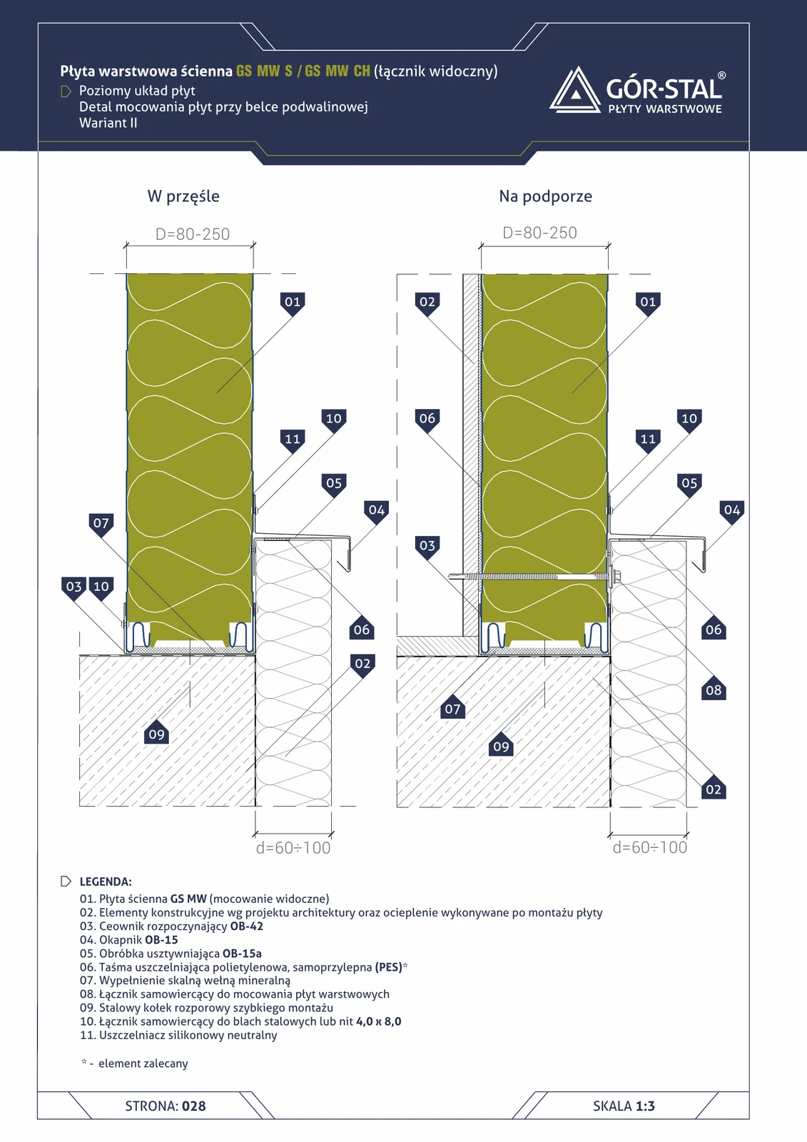
Horizontal plinth variant II = alternative solution with a two-piece OB-15 + OB-15a drip flashing. Chosen when:
- Sill beam is narrower than required for OB-38 (variant I).
- Aesthetics — OB-15 + 15a provide a visually “lighter” drip edge (two thin layers instead of one thick one).
- Better seating — OB-15a = stiffener takes wind loads, OB-15 = waterproof layer.
Functionally the same effect as variant I — safe rainwater drainage + continuity of thermal insulation.
Critical installation aspects
- OB-42 C-profile (item 03) instead of OB-38 Z-profile (variant I); the C-profile is simpler to install (open “U” facing upwards).
- OB-15 + OB-15a — installed in sequence: first OB-15a (stiffener) anchored with expansion plugs to the sill beam, then OB-15 (drip flashing) lapped over OB-15a.
- OB-15 / OB-15a joints sealed with neutral silicone (item 11) and 4.0×8.0 rivets (item 10) every 200 mm.
- Mineral wool (item 07) identical to variant I.
- Choice between variant I vs II — preference of architect vs structural engineer; both provide identical thermal and mechanical parameters.
Documentation
GS MW S/CH/U Technical Catalogue (Gór-Stal 2025), page 26 — Sill plinth, horizontal layout, variant II. Scale 1:5.
Components in this junction
Panel (1)
- 01
Insulation (1)
- 07 Mineral wool
Flashing (3)
- 03 OB-42 starting C-profile (OB-42)
- 04 OB-15 drip flashing (OB-15)
- 05 OB-15a stiffening flashing (OB-15a)
Fastener (3)
- 08
- 09 Steel quick-mount expansion anchor
- 10
Sealant (2)
- 06
- 11 Neutral silicone sealant
Element (1)
- 02 Structural elements per design