Junction function
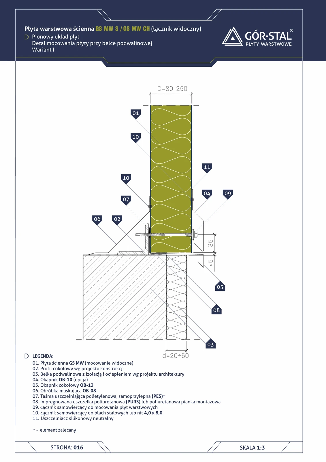
The plinth is the bottom edge of the hall wall — a critical area exposed to rainwater (splash from ground) and capillary moisture (if the sole beam protrudes above grade).
Variant I (projection depth d=20–60 mm) = standard for most industrial buildings:
- Sole beam (item 03) reinforced concrete or steel with insulation (floor pouring, side thermal insulation).
- Plinth profile (item 02) steel, supporting the bottom edge of the panel.
- OB-13 drip flashing (item 05) = plinth flashing with drip edge; projects d=20–60 mm beyond the façade to deflect rainwater.
- OB-10 drip flashing (item 04) optional band at the bottom edge above the plinth (when the façade projects beyond the beam).
- OB-08 trim flashing (item 06) on the interior side conceals the panel-to-beam connection.
Critical installation aspects
- OB-13 projection d=20–60 mm — variant I provides a discreet projection (visually minimal), sufficient for typical conditions (without a large upward façade). For taller walls / heavier rainfall, variant II with d=60–100 mm is recommended (page 17).
- OB-13 → OB-10 joint sealed with neutral silicone (item 11) + 4.0×8.0 rivets (item 10) every 200 mm.
- PURS assembly foam (item 08) in a 5–10 mm band between the sole beam and the panel — seals against capillary moisture rise.
- PES tape (item 07) at the panel joint with the plinth profile.
- Plinth drainage — in areas with groundwater, a drainage grate in a 1 m band along the façade; without it, splash water travels under the building after rainfall.
Used in typical wall systems GS MW S and GS MW CH.
Documentation
Technical Catalogue GS MW S/CH/U (Gór-Stal 2025), page 14 — Plinth at sole beam, vertical panel layout, variant I. Scale 1:5.
Components in this junction
Panel (1)
- 01
Flashing (4)
- 02 Plinth profile per structural design
- 04 OB-10 drip flashing (option) (OB-10)
- 05 OB-13 plinth drip flashing (OB-13)
- 06 OB-08 trim flashing (OB-08)
Fastener (2)
- 09
- 10
Sealant (3)
- 07
- 08 Impregnated PURS gasket or assembly foam
- 11 Neutral silicone sealant
Element (1)
- 03 Sole beam with insulation and thermal insulation