Junction function
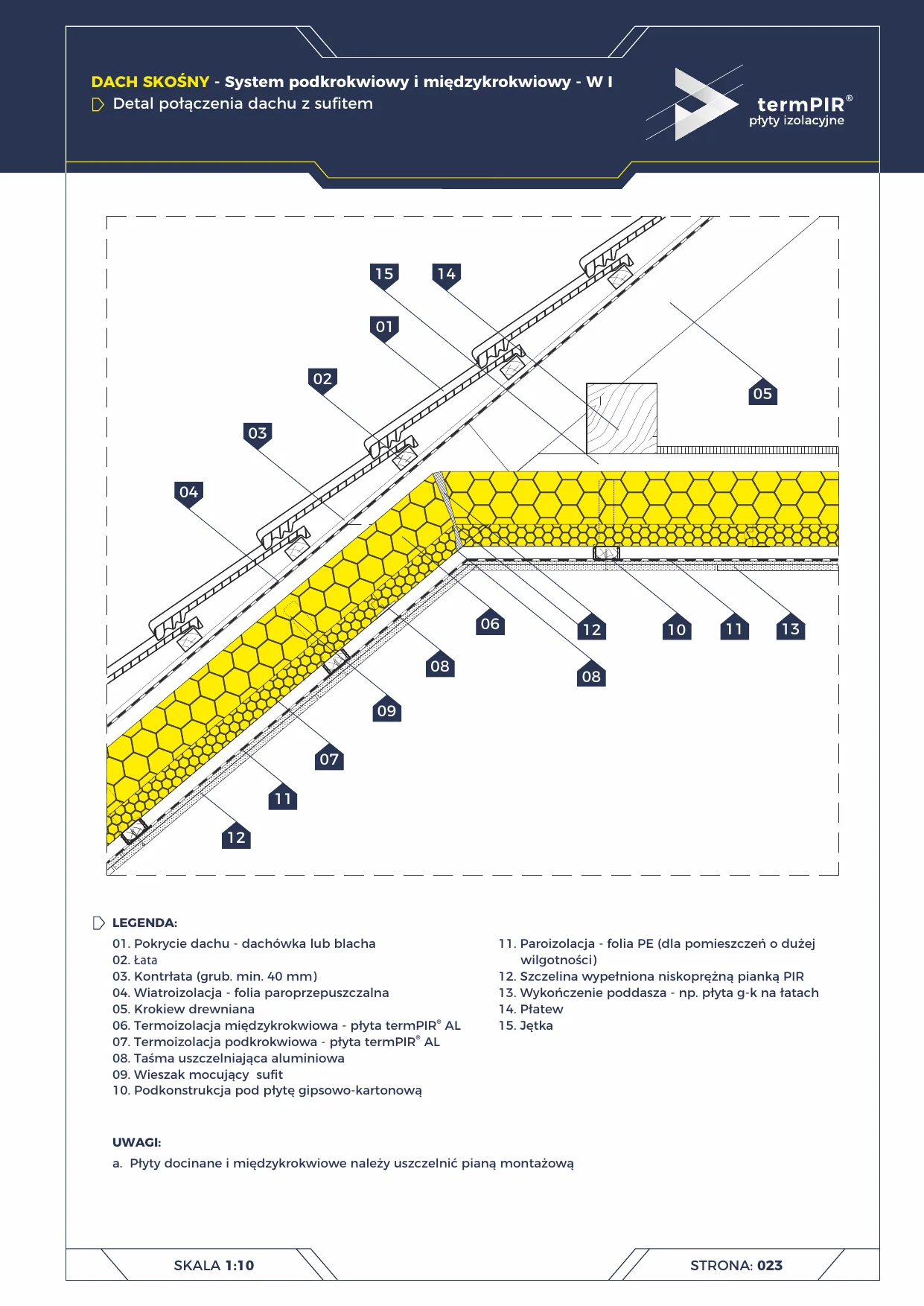
Junction of pitched roof with flat ceiling below the collar beam (15) — a typical detail of habitable attics, where the horizontal part of the ceiling is formed by insulation suspended below the collar beams (15), and the sloped part by under-rafter insulation (07) + between-rafter insulation (06).
A two-layer system (W I) — complete elimination of the rafter thermal bridge:
- Between-rafter layer (06) — between the rafters, insulating the inter-beam space.
- Under-rafter layer (07) — beneath the rafters, eliminating the thermal bridge through the timber of the rafters (timber lambda 0.15 vs PIR lambda 0.022 → ~7× worse).
At the junction with the flat ceiling, both layers must transition continuously onto the ceiling plane — without this, a corner thermal bridge forms at the collar beam.
Critical installation aspects
- Between-rafter thermal insulation (06) — cut to ±2 mm to the between-rafter width. Joints sealed with aluminium tape (08).
- Under-rafter thermal insulation (07) — a second course beneath the rafters fixed to the sub-structure (10). Thickness typically 40–60 mm.
- Horizontal ceiling beneath the collar beam — continuation of the under-rafter termPIR AL on the sub-structure of the ceiling framework (10) — without any break.
- Joint gap (12) slope → horizontal MUST be filled with low-expansion PIR foam. The slope of the panels and their cutting leaves small gaps that form a thermal bridge.
- Vapour barrier (11) continuous from the eaves edge to the collar beam — any break in the vapour barrier → condensation within the insulation.
- Ceiling hanger (09) with a thermal-insulating washer at the penetration point — eliminates a point thermal bridge.
Typical U-value
For termPIR AL 200 mm between rafters + 50 mm under rafters:
- Roof U ≈ 0.10 W/(m²·K) (passive class)
- Rafter thermal bridge Ψ ≈ 0.01 W/(m·K) — with under-rafter insulation
- Without under-rafter layer: Ψ ≈ 0.12 W/(m·K) → 12× greater losses
Used in the under-rafter pitched roof termPIR system.
Documentation
termPIR catalogue — Single-Family Houses, p. 23 — pitched roof W I, junction with ceiling.
Components in this junction
Panel (2)
- 06
- 07
Fastener (1)
- 09 Ceiling suspension hanger
Sealant (2)
- 08
- 12 Gap filled with low-expansion PIR foam
Element (10)
- 01 Roof covering — tile or sheet metal
- 02 Batten
- 03 Counter-batten (min. 40 mm thick)
- 04 Wind barrier — vapour-permeable membrane
- 05 Timber rafter
- 10 Sub-structure for plasterboard
- 11 Vapour barrier — PE film (for rooms with high humidity)
- 13 Attic finish — plasterboard on battens
- 14 Purlin
- 15 Collar beam