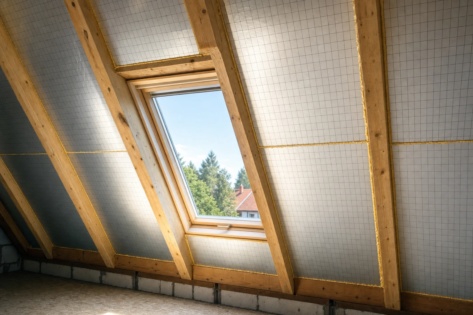
When to use this system
The under-rafter + between-rafter system (W I) is used as an alternative to the over-rafter system:
- Renovations of existing roofs — without the need to remove the roof covering, installation possible from the inside in an occupied building.
- Attic conversions for residential use — when we want to use the existing roof structure without external changes.
- Limited room heights — when over-rafter insulation does not fit due to adjacent objects or regulations.
- Renovations of historic buildings — when interference with the roof covering is not permitted by conservation requirements.
Two-layer arrangement — rationale
The between-rafter layout alone (without an under-rafter layer) reduces efficiency by 15–25% due to thermal bridges at the timber rafters (λ of wood ~0.14 vs λ of PIR 0.022). Therefore the full W I system includes:
| Layer | Function | Minimum thickness |
|---|---|---|
| Between-rafter | filling the space between rafters | 80–160 mm (depending on rafter height) |
| Under-rafter | min. 40 mm — eliminates the thermal bridge at the rafter | 40+ mm |
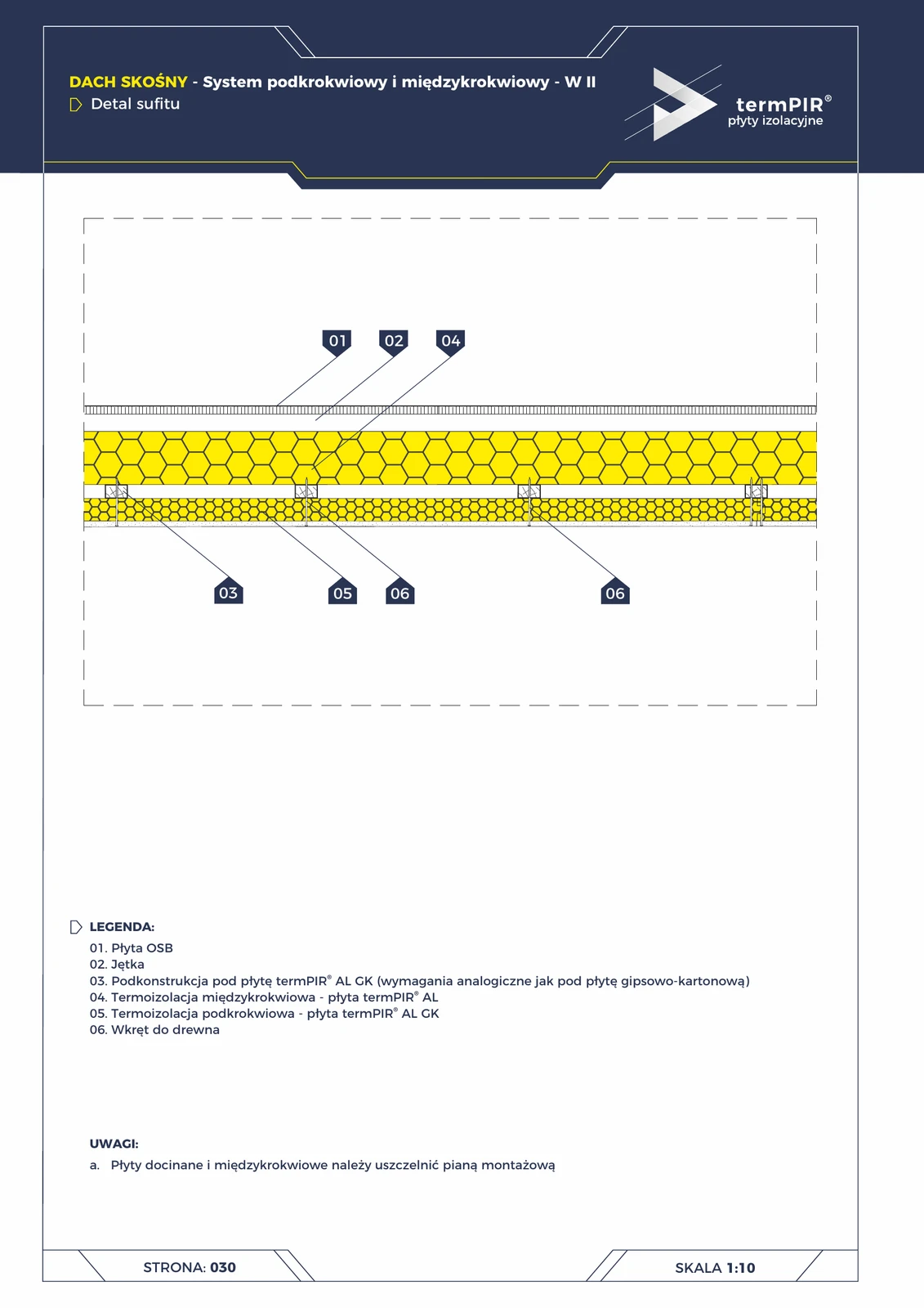
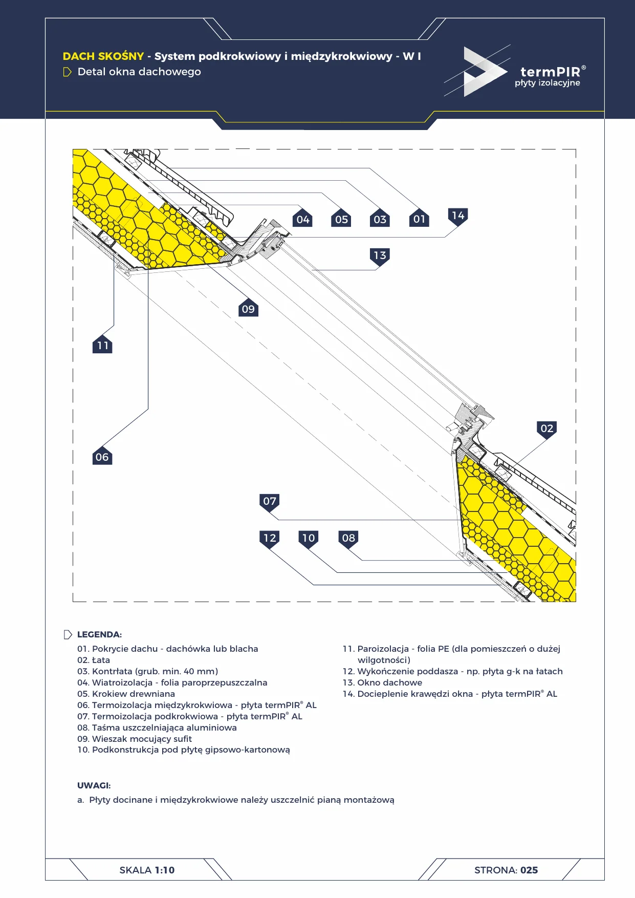
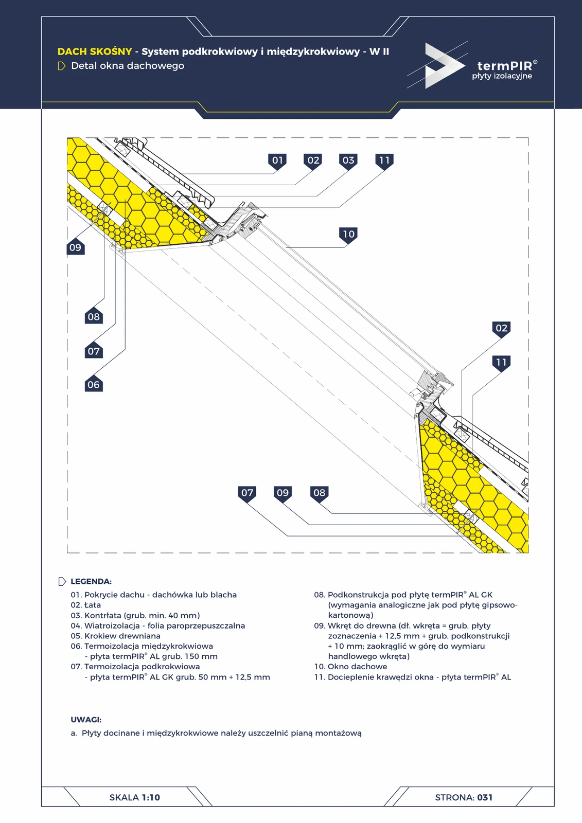
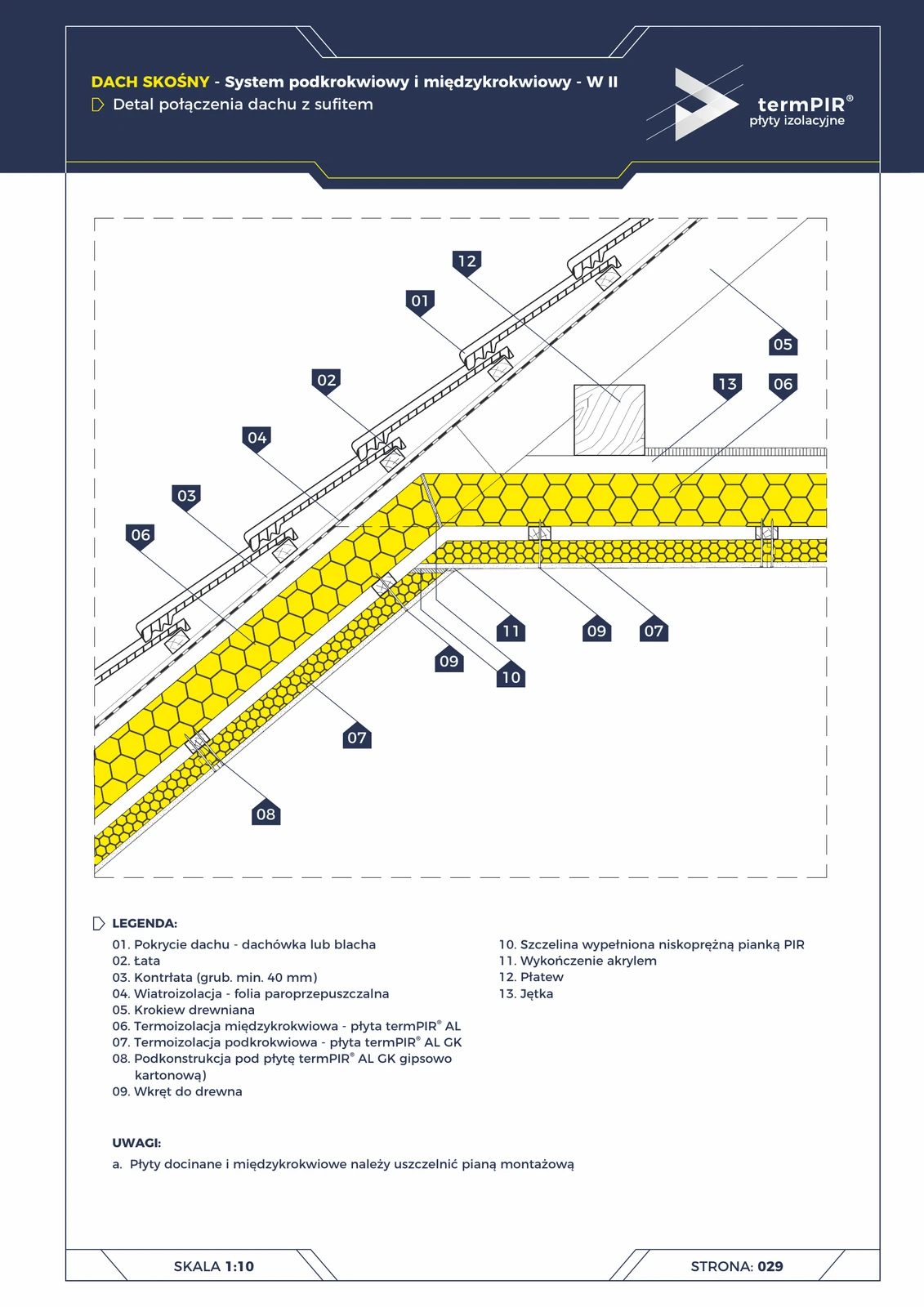
W II variant — with AL GK board
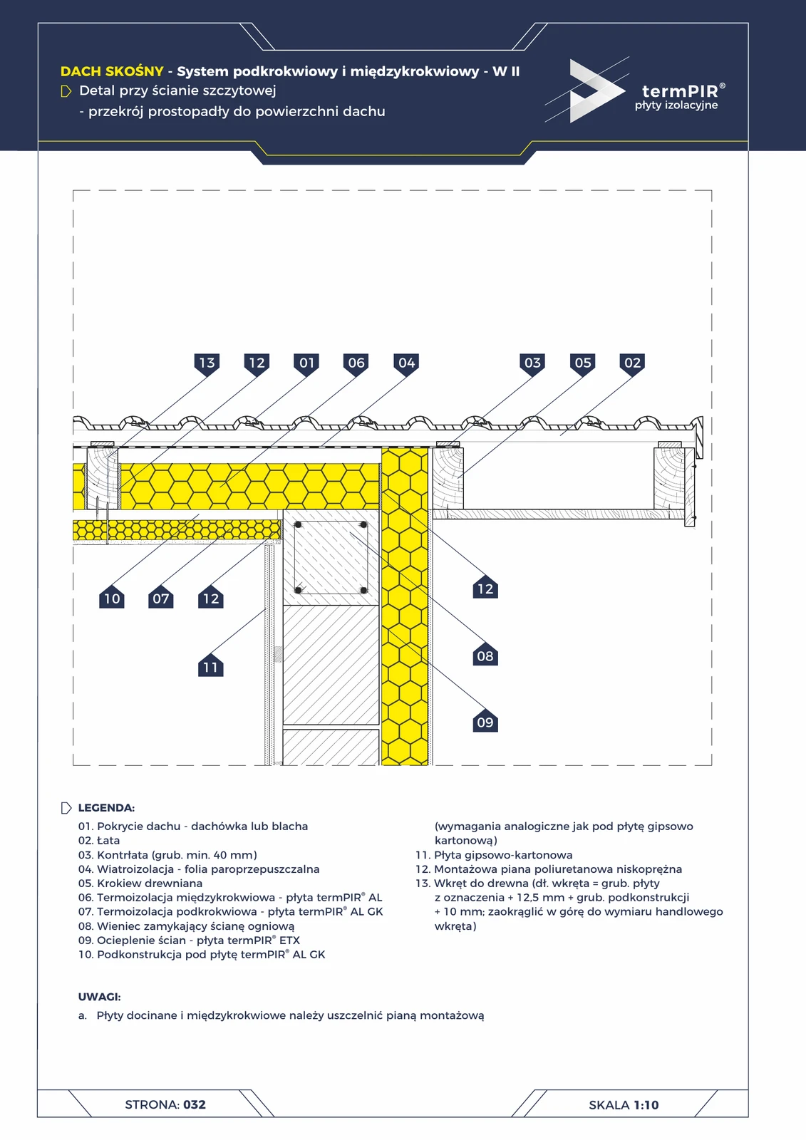
Alternative to W I: instead of a sub-frame + plasterboard, use termPIR® AL GK (a ready-made PIR + plasterboard panel in one) directly on top of the under-rafter layer. Saves a work stage + thinner cross-sections.
Installation requirements
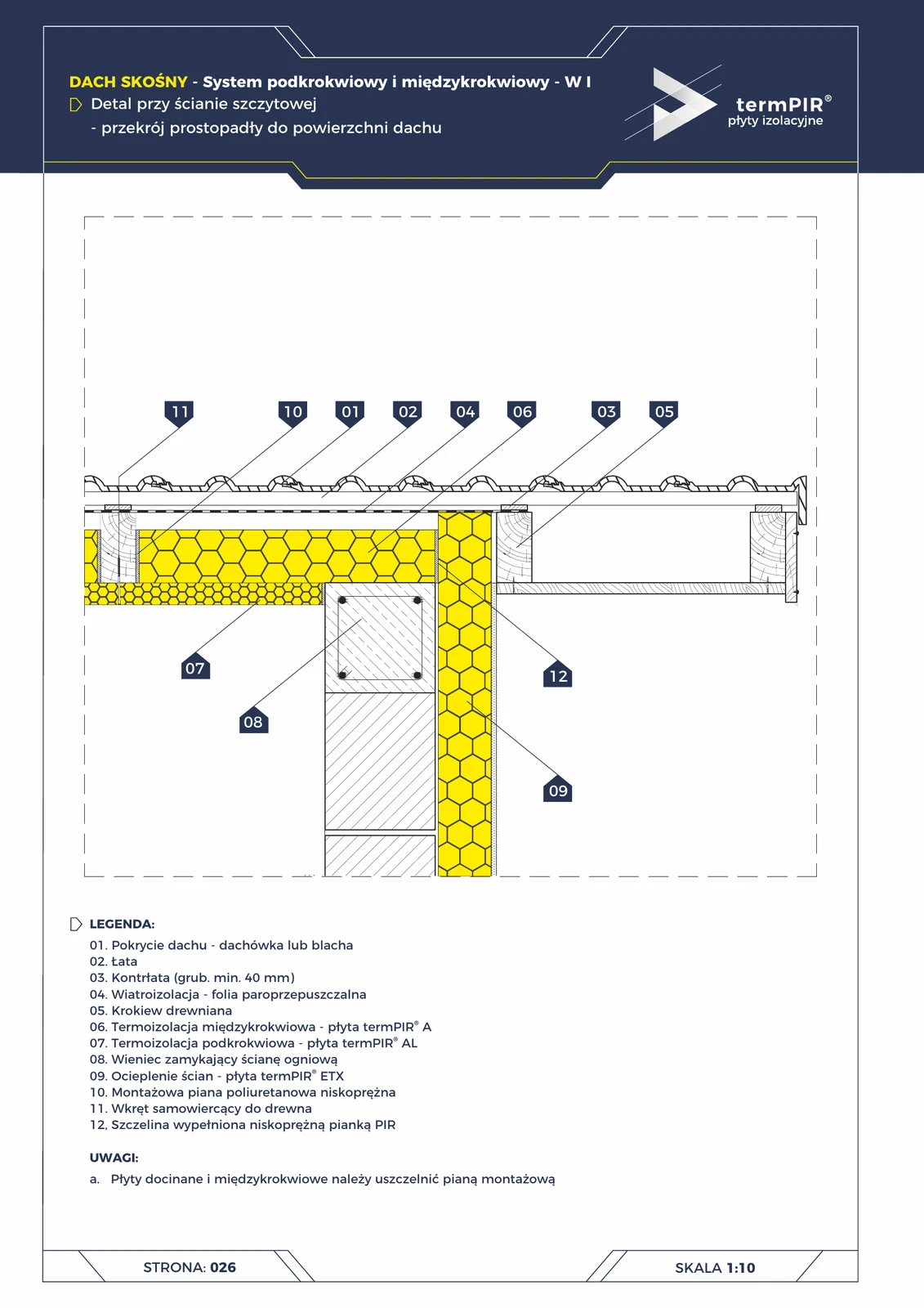
- Edge sealing — all cut edges and edges in contact with rafters of the PIR panels are sealed with low-expansion PIR mounting foam (chemically compatible with the core).
- PE vapour barrier — between the between-rafter and under-rafter layer, tightly taped with butyl tape at joints (prevents condensation in the insulation).
- Under-rafter fixing — timber screws into rafters through the PIR layer, length = PIR thickness + anchoring depth in the rafter (min. 50 mm).
- Ventilation — when renovating old roofs, make sure there is a ventilation gap between the covering and the windproof membrane (min. 25 mm).
Over-rafter vs under-rafter selection
| Aspect | Over-rafter | Under-rafter + between-rafter W I |
|---|---|---|
| Thermal bridges | none (continuous layer) | minimised (under-rafter layer) |
| Interior aesthetics | rafters visible | rafters hidden behind insulation + plasterboard |
| Attic height | unchanged | reduced by ~150 mm (internal layer) |
| Adaptation of existing roof | requires removal of covering | installation from the inside |
| Workmanship | fast (external) | slower, staged |
| Price per m² | higher (better efficiency) | lower (smaller PIR thickness) |
Technical documentation
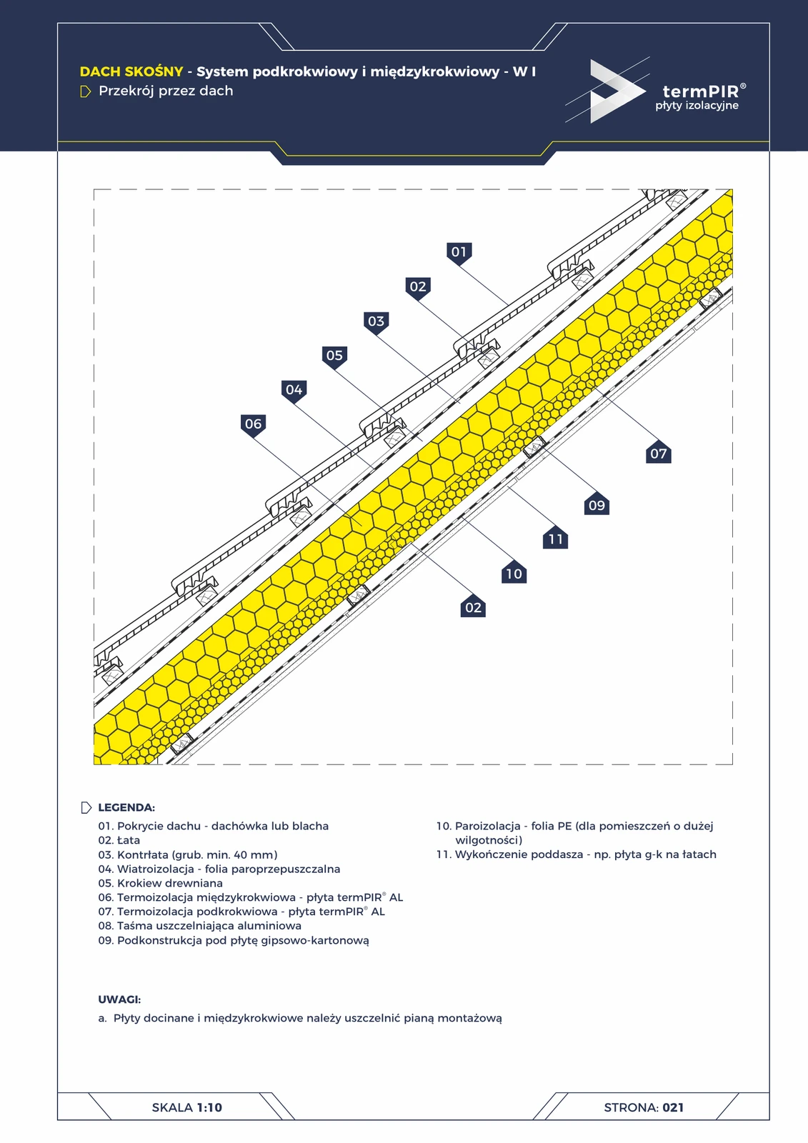
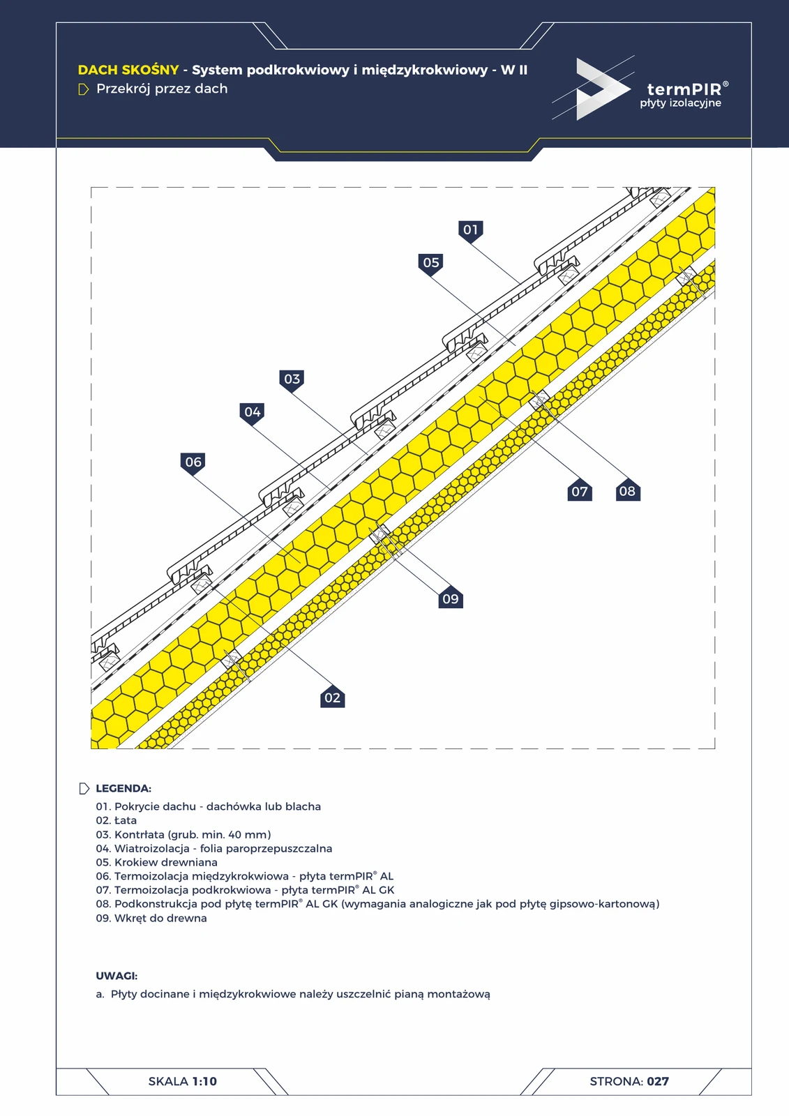
termPIR® catalogue — Residential Buildings (Gór-Stal, 2022-04-26, pp. 21–25). Describes variants W I (rafters visible under insulation finished with plasterboard) and W II (with AL GK board as a ready-made finishing surface).
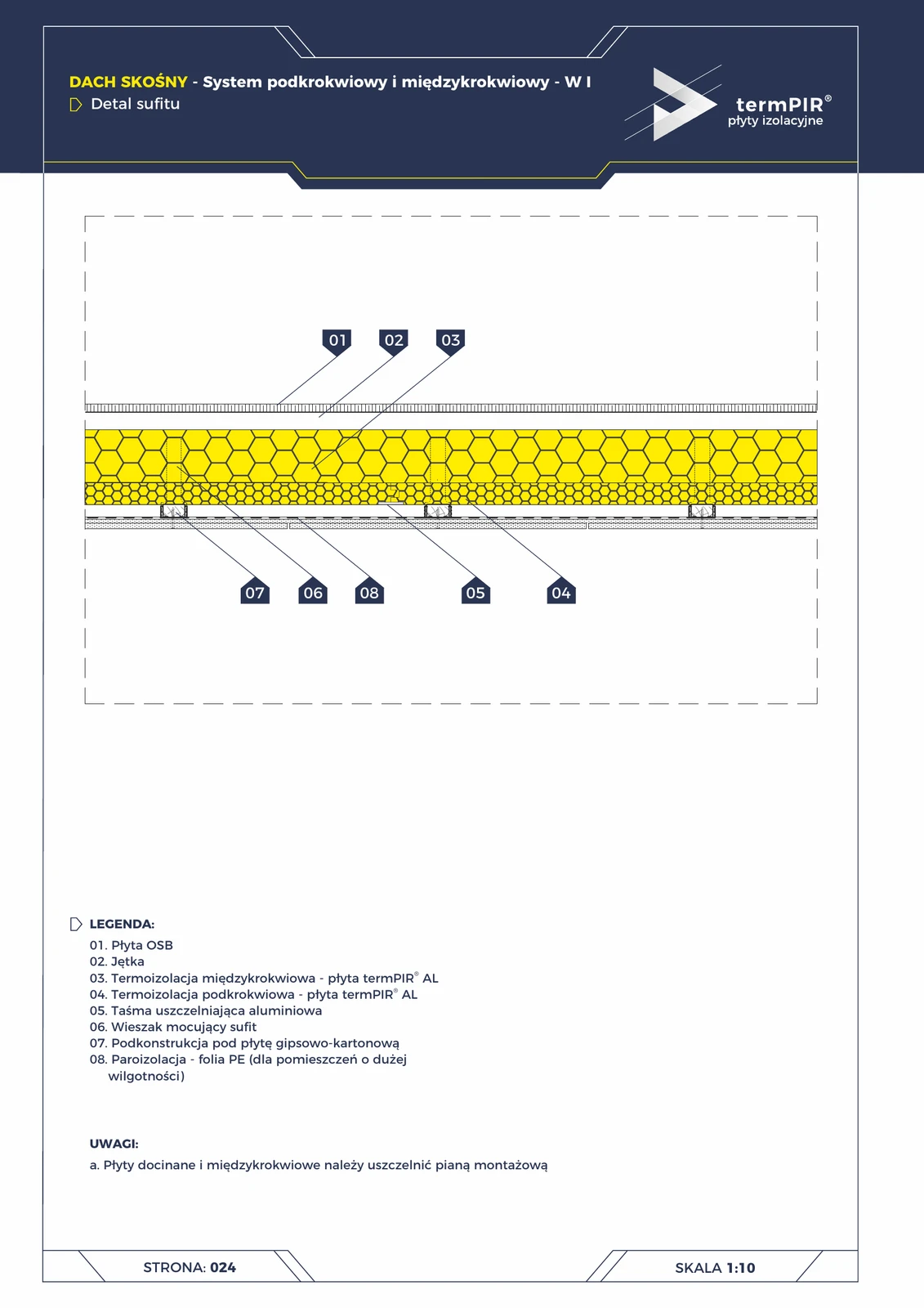
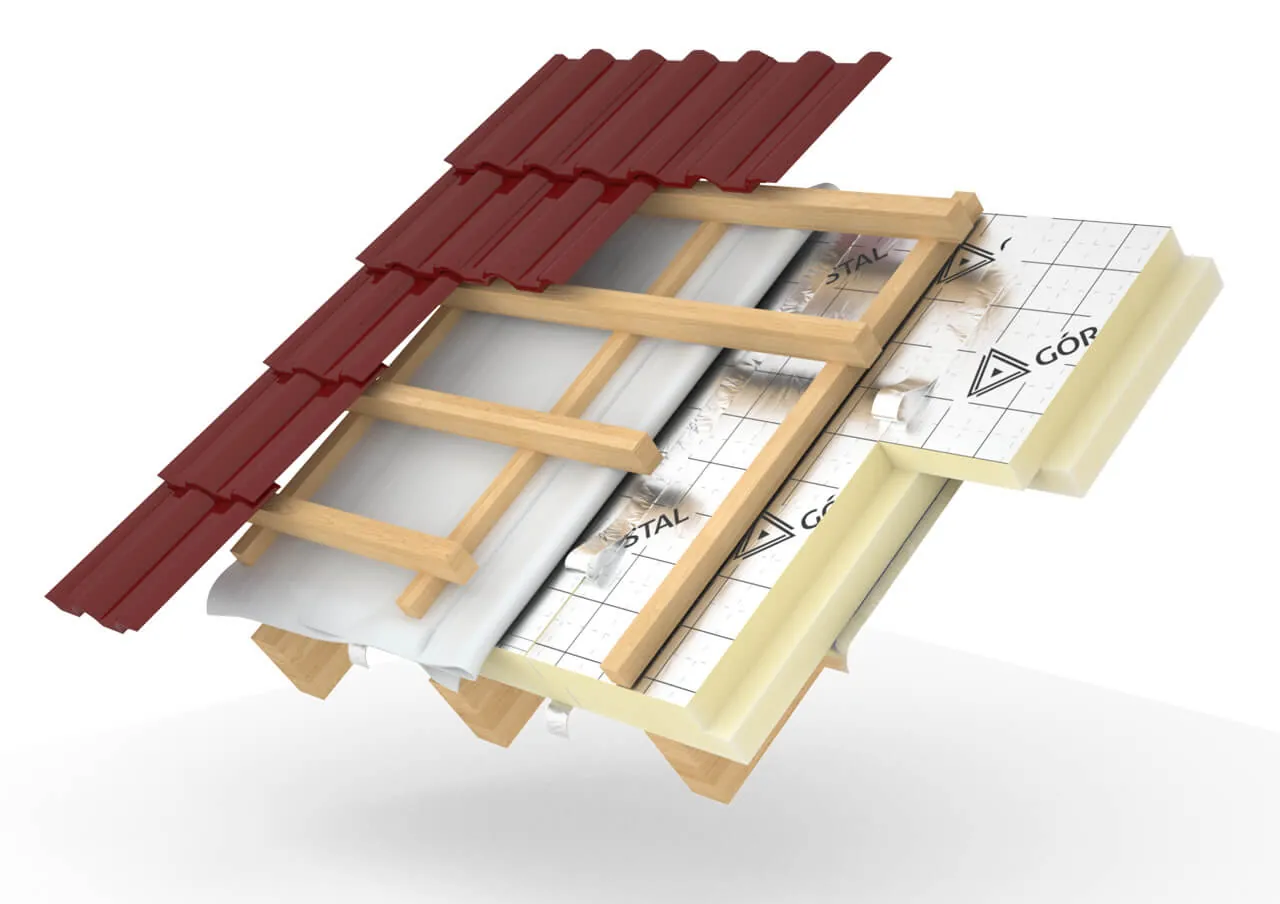
Layer composition
| # | Layer | Thickness | λ | Role |
|---|---|---|---|---|
| 1 | Roof covering — roof tiles or metal sheet | — | — | external covering |
| 2 | Batten + counter-batten | — | — | covering structure |
| 3 | Vapour-permeable windproof membrane | — | — | wind barrier |
| 4 | Timber rafter | — | — | load-bearing roof structure |
| 5 | termPIR® AL (between-rafter layer) | 80–160 mm | 0,022 W/(m·K) | filling the space between rafters |
| 6 | PE vapour barrier | — | — | water vapour barrier |
| 7 | termPIR® AL (under-rafter layer) | 40–100 mm | 0,022 W/(m·K) | insulation eliminating thermal bridge at rafters (min. 40 mm) |
| 8 | Steel or timber sub-frame (battens) | — | — | finishing attachment |
| 9 | Plasterboard panel | — | — | interior finish |
| 10 | Final finish (filler, paint, decorative) | — | — | room finish |
U-value by insulation thickness
| termPIR® thickness | U [W/m²·K] | Meets WT 2021 (roof U ≤ 0.15) |
|---|---|---|
| 120 mm | 0,18 | — no |
| 150 mm | 0,15 | ✓ yes |
| 180 mm | 0,12 | ✓ yes |
| 220 mm | 0,10 | ✓ yes |