Junction function
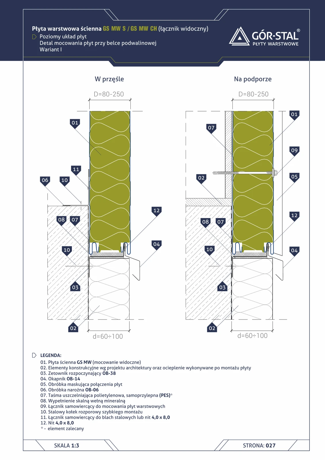
Plinth in horizontal panel layout = bottom row of panels laid horizontally. Vs the vertical layout (p. 16-19):
- OB-38 Z-profile instead of C-profile — guide rail for the bottom edge of the horizontal panel (the panel “rests” on the Z-profile like on a shelf).
- OB-14 drip flashing = plinth trim specific to the horizontal layout (geometrically different from OB-13 used in the vertical layout).
- OB-06 corner flashing at the bottom — finishing of the interior side of the plinth.
Variant I = projection d=60–100 mm — analogous to variant II of the vertical layout (the horizontal arrangement is “by default” wider in projection).
Critical installation aspects
- OB-38 Z-profile anchored with expansion anchors (item 10) to the sole plate beam + 4.0×8.0 rivets to the panel (item 12); anchor spacing every 60 cm.
- Mineral wool (item 08) in the space between the panel and the beam — eliminates the thermal bridge.
- OB-14 drip flashing projects 60-100 mm beyond the façade with a 30 mm drip edge; seal joints with neutral silicone.
- OB-06 internal corner flashing at the bottom — conceals the junction of the horizontal panel with the interior floor.
- Ground slope away from the building — minimum 2% within a 1 m strip to drain rainwater.
Documentation
Technical Catalogue GS MW S/CH/U (Gór-Stal 2025), page 25 — Sole plate plinth, horizontal panel layout, variant I. Scale 1:5.
Components in this junction
Panel (1)
- 01
Insulation (1)
- 08 Mineral rock wool infill
Flashing (4)
- 03 OB-38 starter Z-profile (OB-38)
- 04 OB-14 drip flashing (OB-14)
- 05 Cover flashing for panel joint
- 06 OB-06 corner flashing (OB-06)
Fastener (4)
- 09
- 10 Steel quick-mount expansion anchor
- 11
- 12 4.0×8.0 rivet
Sealant (1)
- 07
Element (1)
- 02 Structural elements per design + insulation