Junction function
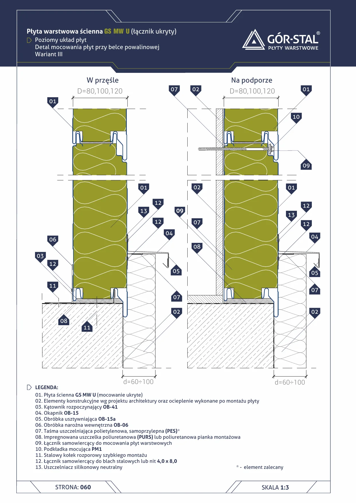
Plinth at sole beam in GS MW U panels (concealed fixing) — start of the façade from the foundation side. It serves three functions:
- Start of the horizontal panel layout — the first panel from the bottom requires an OB-41 starter angle that conceals the panel edge and keeps it vertical.
- Water drainage from the façade — the OB-15 drip flashing directs water running down the façade beyond the plinth line.
- Protection against splash water — the OB-15a stiffener stabilises the drip flashing edge against vibrations from wind and water.
Variant III — for panels 60-100 mm thick. Other variants (I, II, IV) differ in OB-15/15a geometry for thinner or thicker panels.
Critical installation aspects
- Concealed fixing GS MW U — fastener driven through the PM1 fixing washer (item 10) invisibly from the façade side. PM1 eliminates thermal bridges at the fastener.
- OB-41 angle — fixed to the sole beam (item 02) with quick-fix expansion anchors (item 11). The sole beam is typically a steel section or concrete beam.
- OB-15 drip flashing fixed with washer-head fasteners (item 12) or rivets 4.0×8.0 — heads on the façade side aesthetically concealed.
- OB-15a stiffener — additional Z-profile layer under OB-15, eliminates vibrations and wind-induced deformation.
- PURS gasket or assembly foam (item 08) fills the internal space of OB-41 and ensures thermal continuity with the beam insulation.
- Neutral silicone (item 13) on the external joint between OB-15a and the plinth façade — UV- and moisture-resistant.
Horizontal vs vertical layout
| Aspect | Horizontal layout (this one) | Vertical layout |
|---|---|---|
| Aesthetics | linear horizontal pattern | linear vertical pattern |
| Panel joints | between storeys | between modules |
| Plinth | requires OB-41 + OB-15 | requires bottom and plinth flashing |
| Longer panels | yes (typically 8-12 m) | no (max 4-6 m façade height) |
| Price | baseline | +5-10% (more edges around windows) |
Used in the non-combustible GS MW U wall system.
Documentation
GS MW catalogue (Gór-Stal, 2025), p. 60 — variant III of panel fixing at sole beam.
Components in this junction
Panel (1)
- 01 GS MW U wall panel (concealed fixing)
Flashing (4)
- 03 OB-41 starter angle (OB-41)
- 04 OB-15 drip flashing (OB-15)
- 05 OB-15a stiffening flashing (OB-15a)
- 06 OB-06 internal corner flashing (OB-06)
Accessory (1)
- 10 PM1 fixing washer (PM1)
Fastener (3)
- 09
- 11 Steel quick-fix expansion anchor
- 12
Sealant (3)
- 07
- 08 PURS polyurethane gasket or assembly foam
- 13 Neutral silicone sealant
Element (1)
- 02 Structural elements per design + plinth/kerb insulation