Junction function
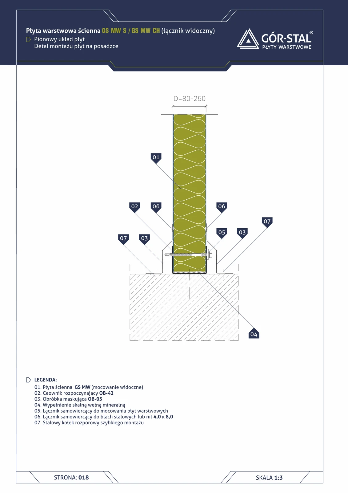
Fixing of vertical panels to a concrete floor — alternative to the plinth on a sill beam (p. 16). Used when:
- The floor is at ground level (without a protruding sill beam).
- Hall with under-floor drainage — water does not reach the panel from below.
- Reinforced concrete floor with waterproofing — full protection against capillary moisture already provided by the floor structure.
Construction:
- OB-42 channel (item 02) = upward-open “U” profile, set on the floor; acts as an installation guide + seal for the lower panel edge.
- Mineral wool (item 04) fills the space inside the channel.
- OB-05 flashing (item 03) conceals the joint on the hall interior side.
- Steel expansion anchors (item 07) — anchor the OB-42 channel to the floor; quick installation (Hilti HUD, Fischer FAZ II).
Critical installation aspects
- Expansion anchor spacing — every 60 cm in the central zone, every 40 cm in the edge zone (1 m from the building corner).
- OB-42 always 30 mm HIGHER than the floor — the waterproofing strip extends beyond the channel; without this, capillary moisture rises into the mineral wool (item 04).
- Mineral wool (item 04) fills the channel space — critical for acoustics (prevents sound transmission through the channel) and fire safety (EI 30 in a hall where REI 30 is required).
- Self-drilling fasteners (item 05) fix the panel to the OB-42 channel; spacing across the 1000 mm panel width — 2 fasteners at the floor + further at the rail.
- No thermal insulation layer beneath the panel = thermal bridge at the floor interface; in a hall heated to +20°C with winter outdoor temperatures of −20°C → condensation at the joint → mould on the inner panel edge. Solution: a 30–50 mm PIR wool strip beneath the channel (when the hall requires U <0.3 for the plinth).
Used in wall systems with vertical layout of GS MW S and GS MW CH panels.
Documentation
Technical Catalogue GS MW S/CH/U (Gór-Stal 2025), page 16 — Panel installation on the floor, vertical layout. Scale 1:5.
Components in this junction
Panel (1)
- 01
Insulation (1)
- 04 Stone mineral wool infill
Flashing (2)
- 02 OB-42 starting channel (OB-42)
- 03 OB-05 trim flashing (OB-05)
Fastener (3)
- 05
- 06
- 07 Steel quick-installation expansion anchor