Junction function
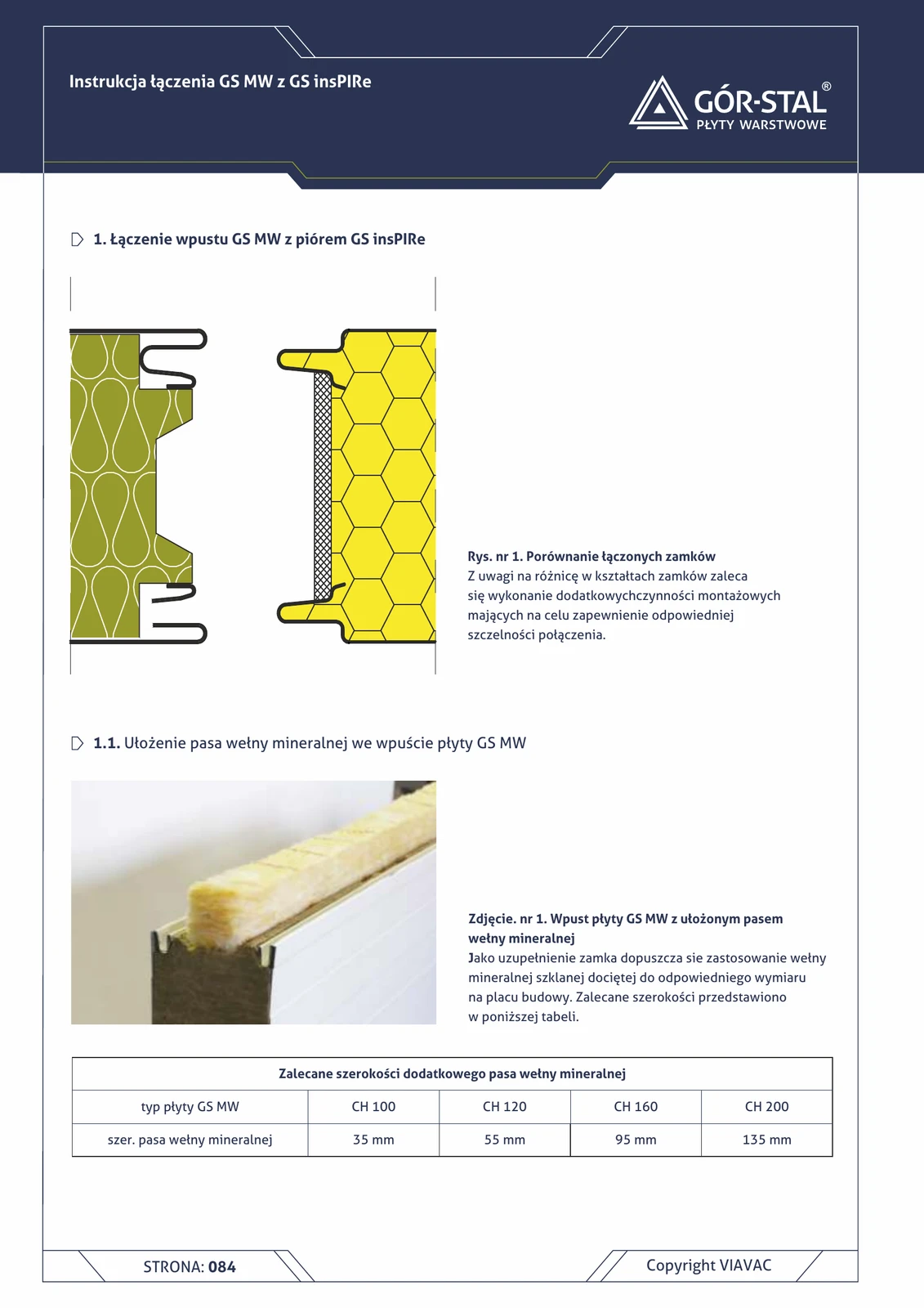
Joint between a GS MW panel and an adjacent GS insPIRe panel — installation detail at the boundary between zones of two sandwich panel systems within a single wall. Used when:
- Fire resistance requirements change within a single wall — lower section REI 60 with MW + upper section with insPIRe.
- Cost optimisation — MW is more expensive than insPIRe; systems are split into zones.
- Retrofit of an existing hall — adding an insPIRe segment to an existing MW wall.
How the tongue-and-groove lock works
Every sandwich panel has a tongue on one edge and a groove on the other — this is the standard tongue-and-groove lock that joins adjacent panels on the façade. These are not two panel types: each GS MW panel and each GS insPIRe panel has both edges (tongue + groove). At the joint between two adjacent panels, the tongue of one always meets the groove of the other.
Which variant this is
At the boundary between MW and insPIRe zones, the joint can occur in two configurations (depending on panel installation orientation):
- This detail — the groove edge on the GS MW side meets the tongue edge on the GS insPIRe side. Easier installation variant.
- Reverse variant — the groove edge on the insPIRe side meets the tongue edge on the MW side (requires trimming the MW tongue with a router): Joint GS MW × GS insPIRe — insPIRe groove + MW tongue.
Technical issue with both variants: the locks of the two systems have different geometries:
- GS MW lock = profile adapted to mineral wool (wide, soft layer).
- GS insPIRe lock = profile adapted to PIR (thinner, rigid layer).
The insPIRe tongue is smaller than the MW groove — the remaining gap must be filled.
Critical installation aspects
- Glass mineral wool strip in MW groove — choose glass (not stone) wool, as it is thinner and softer; it fills the geometric difference between the locks.
- Double-sided butyl tape secures the wool strip in the GS MW groove before inserting the insPIRe tongue edge.
- Air-tightness drops from class 1 per PN-EN 14509 → class 2 or 3 for mixed joints; acceptable in areas without separate climate control.
- Thermal bridge at the joint ~0.03–0.05 W/K per metre of gap — significant for passive buildings, acceptable for typical industrial halls.
- Self-drilling fasteners secure each panel independently to the load-bearing structure (steel rail / column); the joint provides only sealing, not load-bearing capacity.
- OB-17 cover flashing — optional; used where joints are visible on the façade or where aesthetic detailing matters.
- Neutral silicone sealant on the face joint on both the exterior and interior side (after the tongue is inserted).
- Verify manufacturer compatibility — for non-standard projects, early consultation with Gór-Stal is recommended.
The easier installation variant of the two MW × insPIRe joint configurations (variant 2 requires on-site routing of the MW tongue). Used in mixed systems: retrofits and cost/technical hybrids.
Documentation
Technical Catalogue GS MW S/CH/U (Gór-Stal 2025), page 84 — Joint of GS MW groove with GS insPIRe tongue. Scale 1:5.
Components in this junction
- 01
- 02
- 03 Glass mineral wool strip (fills MW groove gap)
- 06
- 05 Self-drilling fastener (panel to load-bearing structure)
- 04 Double-sided butyl tape (secures wool strip in groove)
- 07 Neutral silicone sealant (face joint sealing)