Thermal Imaging Survey: Detecting Thermal Bridges | BOKKA
Thermal imaging — the diagnostic that reveals the truth about insulation
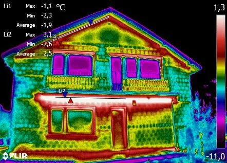
Thermal bridges, discontinuities in the insulation layer, damp sections of building envelope or poorly fitted window joinery can wipe out the effect of even the best energy retrofit. All these defects can be located in a few hours using a thermal imaging camera. More and more investors are commissioning such surveys — both owners of buildings prior to a thermal upgrade, and developers commissioning facilities built with PIR insulation boards of low λD, who want to verify the quality of the contractor’s work. The thermogram is objective evidence — the cold map does not lie.
When to commission a thermal imaging survey — measurement conditions
Reliable results can only be obtained during the heating season, when the temperature difference between the interior and the surroundings is at least 15 K (in accordance with EN 13187 covering qualitative detection of thermal defects in building envelopes). Optimal conditions are:
- outdoor temperature below +5°C, ideally stable for several days,
- no wind (wind speed below 1 m/s — wind cools the surface and distorts the image),
- overcast sky, or measurement at night/early morning (no solar radiation heating the façade),
- no precipitation for at least 12 hours before measurement (a wet envelope changes emissivity).
The interior of the building should be heated to a stable temperature for at least 24 hours before the survey. Any deviation from optimal conditions must be documented by the operator and accounted for when interpreting the thermograms — otherwise the diagnosis loses its evidential value.
How a thermal camera works and what a thermogram shows
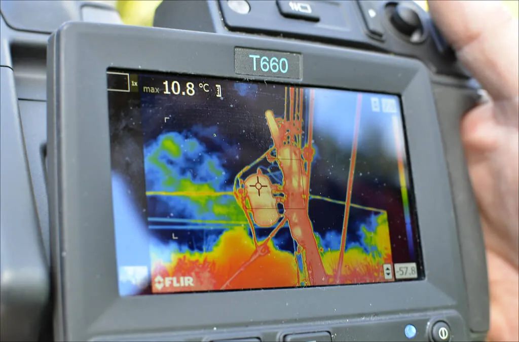
A thermal imaging camera records infrared radiation (in the 8–14 µm range) emitted by any object with a temperature above absolute zero. A microbolometer detector converts the radiation intensity into a surface temperature — with an accuracy of ±2°C or ±2% (professional R&D-class cameras achieve ±1°C). The result is a thermogram: a temperature distribution map presented in a colour palette (most often Iron, Rainbow, Grayscale).
The survey enables:
- visualisation of heat losses through the building envelope,
- detection of damp, damaged or too-thin thermal insulation,
- location of linear thermal bridges (ring beams, lintels, reveals) and point bridges (anchors, fixings),
- identification of structural defects — cracks, leaks, discontinuities in the vapour barrier,
- diagnostics of electrical installations (overheating connections) and underfloor heating (locating loops, leaks).
Surveys are divided into simplified (indicative, several dozen representative thermograms) and full ones with a protocol compliant with EN 13187 — including photographic documentation, description of measurement conditions and emissivity calibration. Only the full version carries evidential value in warranty and court disputes.
What thermograms most often show — typical defects
| Defect | Image on the thermogram | Most common cause |
|---|---|---|
| Linear bridge at ring beam | Horizontal warm line below ceiling slab | No ring beam insulation or layer discontinuity |
| Bridge at window reveal | Warm outline of the window from inside | Insulation not pressed in, no reveal insulation |
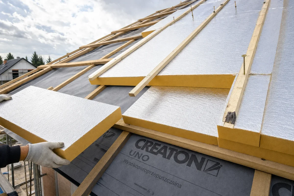
| Roof insulation discontinuity | Patches between rafters | Poorly fitted boards between rafters |
| Dampness | Dark (cool) zone of irregular shape | Leak, condensation, vapour bridge |
| No continuity at board joints | Linear heat leaks along seams | Missing tape or incorrect tongue-and-groove |
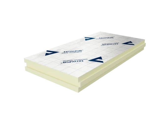
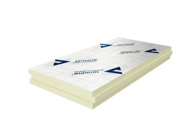
The last point is critical for PIR insulation. Boards with a gas-tight aluminium facing, such as termPIR® AL, require the joints to be sealed with aluminium tape. Skipping the taping leaves linear bridges that appear on the thermogram as a grid.
How a thermogram verifies the effectiveness of PIR insulation
PIR board insulation only achieves its declared performance when the continuity of the layer is maintained and the product is correctly selected for the envelope. A thermal camera allows confirmation that the design has been implemented in compliance with WT 2021 (Polish Technical Conditions 2021):
- roof U ≤ 0.15 W/m²K,
- external wall U ≤ 0.20 W/m²K,
- ground-bearing floor U ≤ 0.30 W/m²K.
With λD = 0.022 W/(m·K) (termPIR® AL), 150 mm is enough to achieve a roof U of ~0.14 W/m²K. The premium version termPIR® MAX 19 AL with λD = 0.019 W/(m·K) achieves the same parameter at 130 mm — important where minimum cross-section thickness matters (terraces, over-rafter roofs above heritage timber trusses).
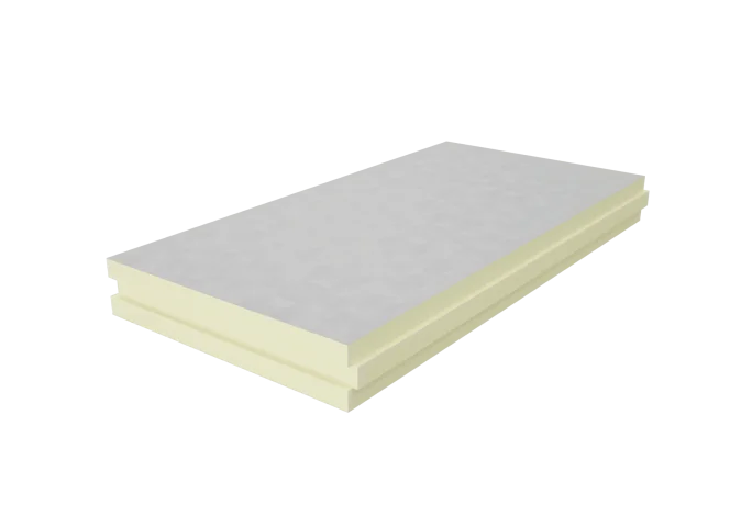
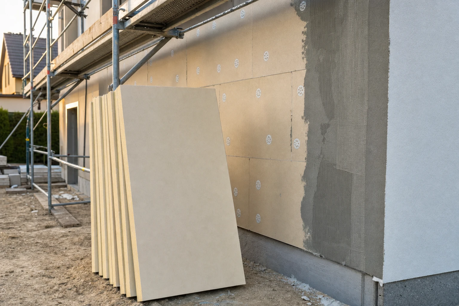
Product selection for the installation method is particularly important. On ETICS systems, thermograms often reveal extensive bridges if the contractor used the wrong facing. For thin-coat renders, termPIR® ETX with glass fleece and ETA 17/0066 is intended — the vapour-permeable facing ensures vapour release and adhesion of both adhesive and render. Foundations and plinths, in turn, require termPIR® WS with enhanced moisture resistance.
Thermography during construction and at handover
A thermogram taken before the insulation layer is covered (e.g. before OSB boards are fitted over rafters, or before render in an ETICS system) makes it possible to detect errors when their repair costs only a few hundred zlotys. The same error revealed a year later — when part of the façade has to be chipped off — pushes the cost to several thousand. Increasingly, a thermal imaging protocol is part of the technical handover in commercial facilities: logistics parks, production halls, premium showrooms. The investor commissions diagnostics by an independent expert and uses it to enforce corrections from the general contractor during the warranty period.
In thermal upgrades of existing buildings, thermography makes it possible to optimise the scope of work — instead of insulating the entire envelope, efforts can focus on critical areas: reveals, ring beams, parapets, balconies. This translates directly into the ROI of the investment.
Frequently asked questions
Can a thermal imaging survey be carried out in summer?
Is a thermogram admissible as evidence in a dispute with the contractor?
Can PIR boards be seen on a thermogram?
How much does a professional thermal imaging survey of a house cost?
Does a thermal bridge always indicate a contractor's error?
Related products and systems
Products
Read next
Smog and Allergies — How PIR Thermal Upgrades Cut Emissions | BOKKA
Energy Retrofit with PIR Boards and WT 2021 in Practice | BOKKA
Retrofitting Old Houses with PIR Boards — Energy Upgrade Guide