Load-bearing capacity and span of sandwich panels — matching thickness to support spacing
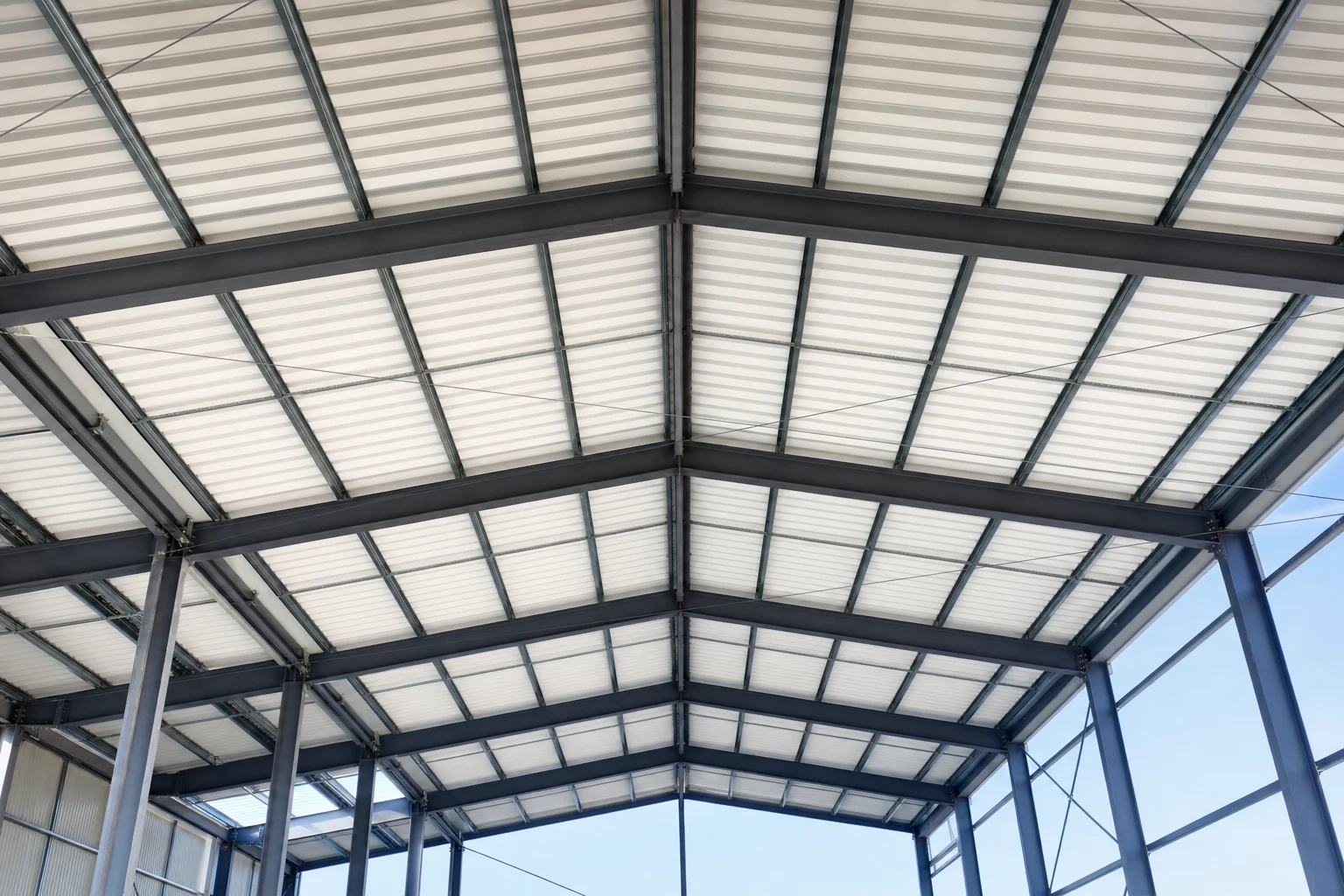
The question “which sandwich panel to choose” in a structural project usually boils down to one thing: what thickness, at what support spacing, will carry the assumed loads without exceeding the capacity or the permissible deflection. This is not a selection done “by eye”, nor a simple function of thickness — the load-bearing capacity of a sandwich panel arises from the cooperation of the core and the facings, the static scheme and the specific combination of loads. In this article we organise the methodology for matching thickness to span: what influences it, how to read the manufacturer tables and where the most common mistakes lurk. We do not quote specific capacity values from memory — these always come from the manufacturer’s current tables for the given product.
How a sandwich panel carries load
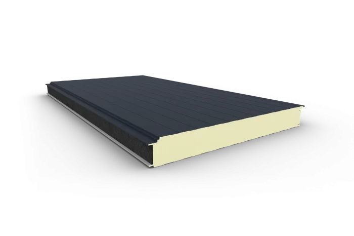
A sandwich panel works like a layered (sandwich) beam: two thin, stiff steel facings carry the bending stresses (one in tension, the other in compression), while the PIR or mineral wool core holds them at a constant distance and transfers the shear stresses. This division of roles is the essence of the construction: bending stiffness is governed above all by the distance between the facings, i.e. the core thickness.
From this follow four pillars of load capacity:
- Core thickness — the greater it is, the higher the section’s moment of inertia and the smaller the deflection. This is usually the strongest lever of capacity.
- Type and thickness of the facings — they carry the normal stresses; their thickness and profiling (especially in roof panels) affect capacity and resistance to local buckling of the compressed facing.
- Shear strength and stiffness of the core — the core must transfer the transverse forces and prevent loss of cooperation between the facings; this is where PIR and mineral wool cores differ.
- The static scheme — support spacing and number of spans, more on which below.
What actually loads the panel
Selection starts from collecting the loads, not from the catalogue. For a sandwich-panel envelope, the governing loads are usually:
- snow load — key for roof panels, dependent on the snow zone and roof geometry;
- wind pressure and suction — important for walls, but for roofs suction can even be decisive, because it lifts the panel off its supports and loads the fasteners and the external facing in a different direction than snow;
- erection and service loads — e.g. a concentrated load from a person moving across the roof during installation;
- self-weight plus any additional loads (services, panels).
Only the set of these loads in the appropriate combinations decides which thickness is permissible at a given spacing. Some loads (suction, snow) change direction or the critical point, which is why the same panel may have different permissible spans for different scenarios.
Single- and multi-span — why the scheme changes the result
The manufacturer tables distinguish static layouts, because these determine the distribution of forces:
- Single-span layout (a panel on two supports) — the maximum moment occurs at mid-span and the deflections are largest. The scheme is simple and safe to interpret, but less “economical”: for a given thickness it allows a smaller span.
- Multi-span / continuous layout (a panel running over three or more supports) — usually allows larger spans at the same thickness, because continuity reduces the mid-span moment and deflection. However, a support moment appears, compressing the facing over the support — and under wind suction that same facing can be the critical point (local buckling, crushing of the core over the support). For a continuous scheme, therefore, the decisive point is often not the mid-span but the support zone.
The practical conclusion: you must not transfer a span from a single-span table onto a real continuous layout (or vice versa). You have to read the table for the actual scheme and for both signs of load (snow “downward”, suction “upward”).
Capacity vs deflection — two different criteria
A panel may be “strong enough” and yet unsuitable for use — if it deflects beyond the permissible limit. Two limit states work in parallel in selection:
- ultimate limit state (ULS) — whether the panel will not fail (crushing of the core, buckling of the compressed facing, shear failure, fastener pull-out);
- serviceability limit state (SLS) — whether the deflection and any effects (e.g. from a temperature difference between the facings) stay within permissible limits, usually expressed as a fraction of the span.
Often it is precisely deflection that limits the span sooner than strength — particularly with thinner cores and long spans. That is why manufacturer tables usually give values limited by one criterion or the other, and selection consists of reading off the more restrictive limit.
Wall panel vs roof panel — these are different tools
A common mistake is treating all sandwich panels as interchangeable. In fact:
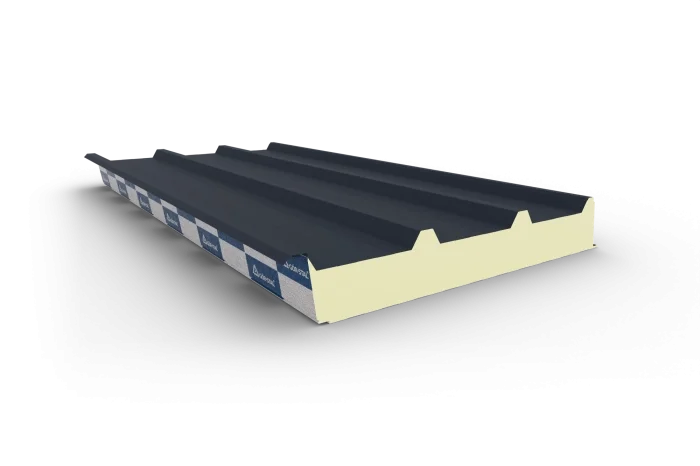
- roof panels (insPIRe D) are designed for loads perpendicular to the slope (snow, suction, erection load), have a profiled external facing that increases stiffness, and their own span tables for the roof;
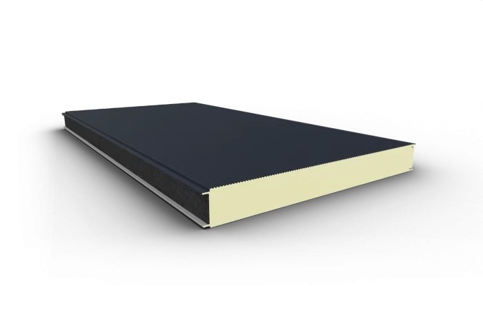
- wall panels (insPIRe S) and hidden-fix panels (insPIRe U) mainly carry wind pressure and suction and self-weight, and their tables refer to the spacing of the wall rails.
A partition panel (internal wall) and a load-bearing roof panel are two different structural tasks — you should not assume that a wall type will “carry” a roof function. A full overview of the variants and their applications is covered in our text on the lightweight envelope from sandwich panels.
Selection methodology — step by step
In design practice, matching thickness to span proceeds as follows:
- Define the function and panel type — roof, wall, visible or hidden fixing, and possibly a fire-resistance requirement (this may narrow the available thicknesses and core).
- Collect the loads — snow zone, wind zone and exposure (pressure/suction), erection loads; establish the combinations to standards.
- Establish the static scheme — support spacing and number of spans (single- or multi-span); this selects the right table.
- Adopt the deflection criterion — the permissible limit follows from the standard and the building’s requirements.
- Read from the manufacturer tables the permissible span or minimum thickness for the given combination of load × scheme × criterion — and choose the most restrictive case.
- Check the fasteners and support zones — especially under wind suction.
In this chain, the numerical values come from the load tables of the specific product, declared by the manufacturer in accordance with EN 14509. They should not be reconstructed from general formulas or transferred between different panel types — these differ in core, facing and profiling. A comparison of envelope weight and capacity at the scale of a whole building is shown using the example of a 1000 m² hall: termPIR or sandwich panels.
Summary
The load-bearing capacity of a sandwich panel is a resultant, not a single figure: core thickness gives stiffness, the facings carry the stresses, the static scheme distributes the forces, and the loads — especially wind suction and snow — determine the governing case. A thicker core usually allows a larger span, but the final limit follows from the manufacturer tables and often from the deflection criterion, not strength. That is why we begin selection from function and loads, and finish with the right span table for the actual scheme — not with intuition.
🤝 Contact a BOKKA technical adviser — give us the support spacing, the snow and wind zone and the function of the envelope, and we will select the sandwich panel type and thickness from the manufacturer load tables and confirm it with the product documentation.
Sources:
- EN 14509 — Self-supporting double skin metal faced insulating sandwich panels (requirements, tests, declared capacities)
- Manufacturer load and span tables for the given panel type (product data)
- Eurocode 1 (EN 1991) — actions on structures: snow and wind loads
Frequently asked questions
What does the load-bearing capacity of a sandwich panel depend on most?
How does a single-span panel differ from a multi-span one?
Does a thicker panel always mean a larger permissible span?
Can a wall panel act as a load-bearing roof panel?
Related products and systems
Read next
Installing sandwich panels in autumn and winter — what works and what to watch

Car wash — building with sandwich panels and the cost of a moisture- and chemical-proof envelope
The most common sandwich panel installation mistakes — what to watch on site