Thermal Bridges — How to Eliminate Them with PIR Boards (WT 2021)
Thermal bridges — the energy cost that doesn’t show up on the drawings
Thermal bridges are local discontinuities in the insulation layer where heat flux travels significantly faster than through the adjacent assembly. In buildings designed without a detailed analysis of construction details, they are responsible for as much as 20–30% of total heat loss through the building envelope, and in nearly zero-energy buildings (nZEB) their proportional share grows as the U-value of standard assemblies decreases. In the context of the WT 2021 (Polish Technical Conditions 2021) — which require U ≤ 0.15 W/m²K for the roof and U ≤ 0.20 W/m²K for the external wall — eliminating thermal bridges becomes a necessary condition for meeting both the U-value and the EP indicator. The most effective method is to design a continuous, rigid insulation layer with a low lambda value — namely PIR insulation boards from the termPIR® family.
What exactly is a thermal bridge — definition and classification
According to EN ISO 14683, a thermal bridge is a section of the building envelope where the one-dimensional heat flow model is no longer adequate — heat flux becomes two- or three-dimensional. Two basic types are distinguished:
- Linear thermal bridges (Ψ, [W/(m·K)]) — occur along a line: wall-to-roof junctions, ring beams, lintels, window reveals, parapets, balconies, plinths.
- Point thermal bridges (χ, [W/K]) — generated by mechanical fasteners, anchors, brackets and structural penetrations.
While point thermal bridges (e.g. ETICS fasteners) typically raise the U-value of an assembly by 0.01–0.03 W/m²K, an uncompensated linear thermal bridge at a slab-to-wall junction can degrade the effective U-value of an entire segment by 15–25%. In addition, local cooling of the internal surface below the dew point leads to water-vapour condensation, structural dampness and mould growth — with both health and structural consequences.
Typical thermal-bridge locations and their scale
In Polish design practice, the most common linear thermal bridges are:
| Location | Typical Ψ [W/(m·K)] uncorrected | Main cause |
|---|---|---|
| Ring beam below window | 0.30–0.60 | No insulation over-pour |
| Window reveal flush with wall | 0.10–0.25 | Joinery outside insulation layer |
| Wall-to-pitched-roof junction | 0.15–0.40 | Insulation broken at the wall plate |
| Cantilever balcony slab | 0.60–1.00 | Concrete acting as linear bridge |
| Plinth / foundation | 0.40–0.80 | No plinth or foundation-wall insulation |
| Flat-roof parapet | 0.30–0.70 | Reinforced concrete extending above insulation |
Each of these details requires a dedicated design solution — most often based on maintaining continuity of the insulation layer with the lowest possible lambda.
Why PIR boards are the optimal material for eliminating thermal bridges
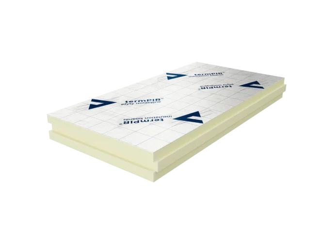
Rigid polyurethane (PIR) boards compliant with EN 13165 have three features that determine their effectiveness in critical details:
- Low lambda — termPIR® AL has λD = 0.022 W/(m·K), and termPIR® MAX 19 AL reaches λD = 0.019 W/(m·K). For comparison, mineral wool ranges 0.035–0.040 W/(m·K) and EPS 0.031–0.040. This means that 30 mm of PIR delivers thermal resistance comparable to ~55 mm of mineral wool — invaluable wherever space for insulation is limited (window reveals, parapets, lintels).
- Dimensional stability and rigidity — the board does not settle or deform under the weight of finishing layers, so joints remain tight throughout the building’s lifecycle.
- Low water absorption — the closed-cell PIR structure (>90%) means the material does not lose its thermal performance under moisture, which is critical in plinth and foundation zones.
A 100 mm thickness of termPIR® AL provides R ≈ 4.55 m²K/W, which translates to U ≈ 0.22 W/m²K for a typical masonry wall — a starting point for further optimisation.
Construction details — where PIR solves the problem
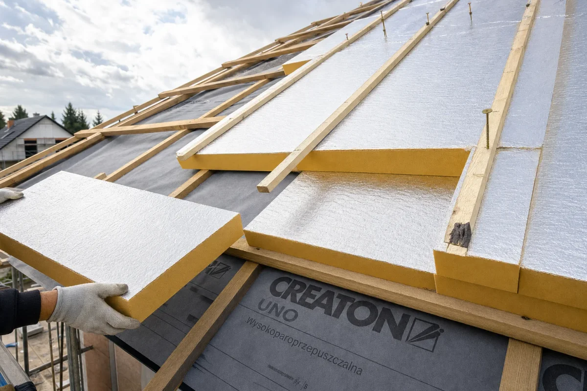
Pitched roof — over-rafter insulation
Classic between-rafter insulation generates linear thermal bridges along every rafter (Ψ ≈ 0.05–0.10 W/(m·K) × rafter length). Over-rafter termPIR® AL insulation creates a uniform layer above the timber structure, completely eliminating rafter bridges and achieving U ≤ 0.15 W/m²K at just 160–180 mm thickness.
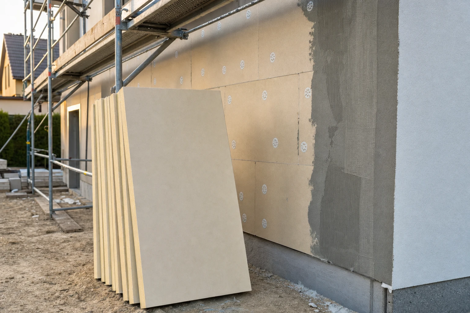
External wall ETICS
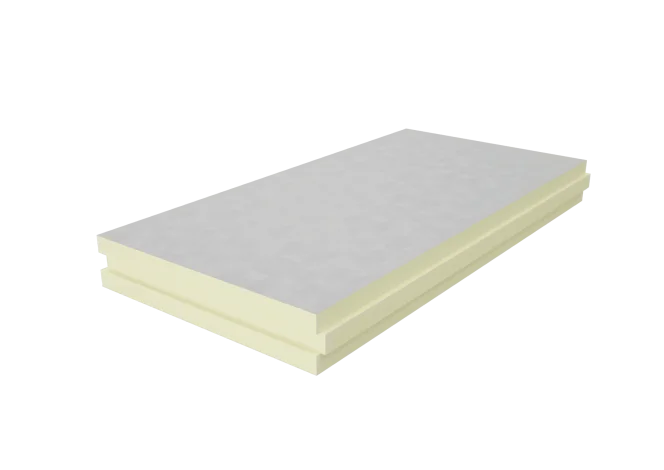
ETICS systems require a vapour-permeable facing — we use termPIR® ETX with a glass fleece and ETA 17/0066 approval. PIR boards allow the insulation thickness to be reduced by 30–40% compared with EPS at the same U-value, which translates into shorter fasteners, smaller point thermal bridges (χ) and less loaded window reveals.
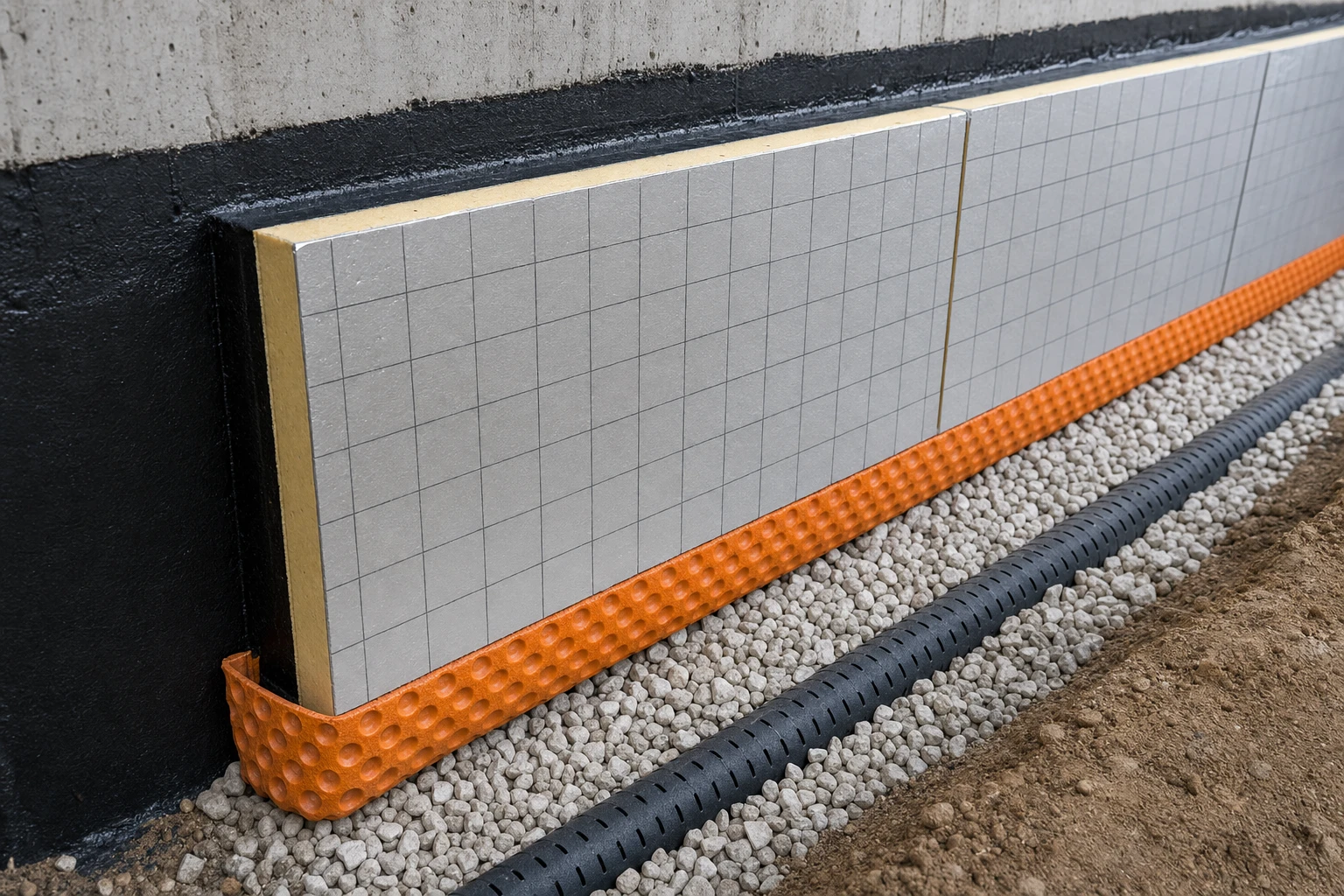
Plinth and foundation
termPIR® WS insulation, with enhanced moisture resistance, ensures thermal continuity from the foundation footing through the foundation wall up to the ETICS layer — eliminating one of the most significant plinth thermal bridges. The three-layer foundation variant makes it possible to achieve Ψ < 0.10 W/(m·K) at the floor-to-wall junction.
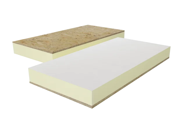
Two-layer “staggered” installation
For insulation thicknesses above 160 mm, a two-layer arrangement is recommended, with joints offset by at least 150–200 mm in both axes. This eliminates thermal bridges through intersecting joints — a small detail of major significance, especially for insulation over timber structures. For frame and floor applications, it is worth considering termPIR® AL/OSB composites, which combine insulation with a ready-to-use working layer.
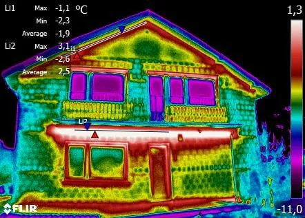
Quality control — thermography and Ψ calculations
Designed elimination of thermal bridges should be verified in two stages: at the design stage through Ψ calculations using 2D software (THERM, Flixo, AnTherm) in accordance with EN ISO 10211, and at the handover stage through thermographic testing per EN 13187. Good workmanship practices include sealing joints with aluminium tape, filling gaps with low-expansion PUR foam, and photographically documenting successive layers.
Frequently asked questions
Can PIR boards be used in every building assembly?
How thick do PIR boards need to be to comply with WT 2021?
Can thermal bridges be eliminated in an existing building?
How does termPIR® AL differ from termPIR® ETX?
Which standards govern the design of thermal bridges?
Related products and systems
Products


Read next

Energy Retrofit with PIR Boards and WT 2021 in Practice | BOKKA

Retrofitting Old Houses with PIR Boards — Energy Upgrade Guide
Smog in Poland & Thermal Upgrades — the Role of PIR Boards | BOKKA