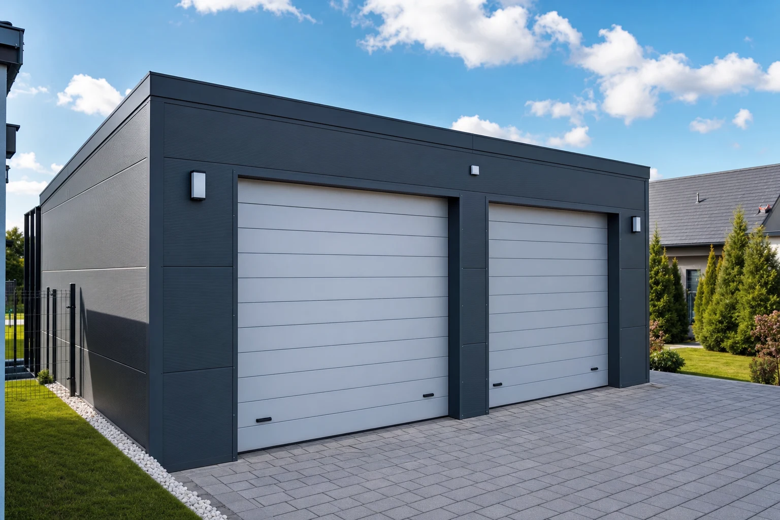
Sandwich panel flashings — a map of details from plinth to ridge
Monday, shortly after eight. You open the hall after the weekend and see a dark streak on the floor — right under the ridge. It was windy overnight, with driving rain. The roof is two years old, the panels are fine, the contractor swears he screwed everything down properly. And he probably did. It is just that a sandwich panel envelope almost never leaks through the panel. It leaks through the details.
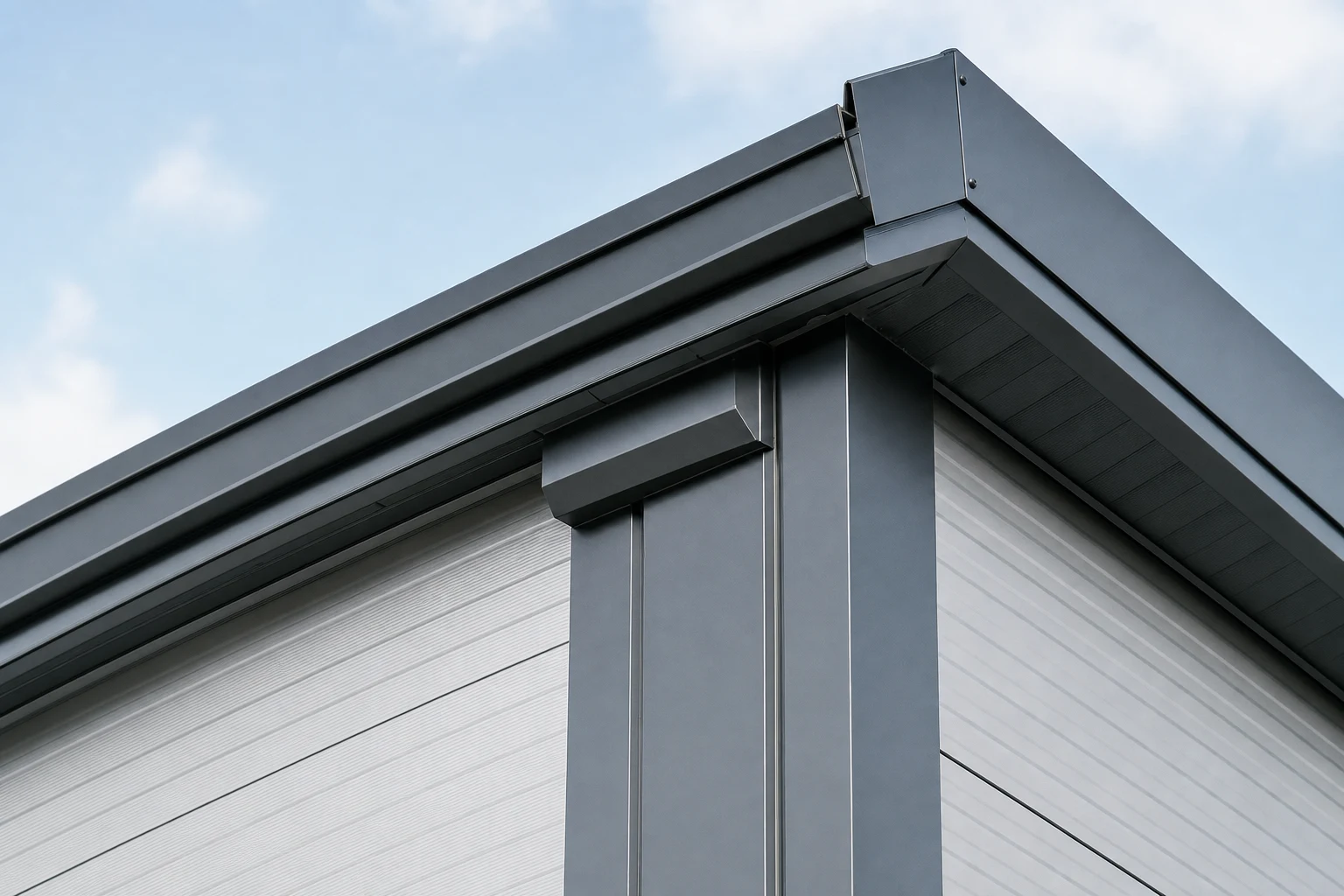
Those details are the sheet metal flashings for sandwich panels — bent from sheet: drip flashings, corner trims, verge flashings and ridge combs. In this article we walk the building zone by zone, from plinth to ridge, with the names and codes of the elements straight from the manufacturer’s technical catalogue.
Why a flashing at all, if the panel has a lock?
The panel lock seals the longitudinal joint — and does it well. But a building does not consist solely of longitudinal joints. It has corners, roof edges, openings for doors and windows, the place where the wall meets the foundation. At each of these points the panel facings end and the core is left exposed.
The flashing does four things at once in these places. It guides water — like a miniature gutter profiled precisely for the given detail. It closes the joint against wind, which at a wall can push rain upwards, against gravity. It shields the gaskets from the sun — over time, UV radiation crumbles exposed foam and sealants. And finally, only finally, it masks the fasteners and cut edges so the whole thing looks as it should.
That is why well-chosen sandwich panel flashings are not an extra cost but part of the building envelope. The guide to building a hall from sandwich panels in fact treats them as a fixed item in every quotation.
The plinth — where installation starts, and where trouble starts
The first wall panel stands on the plinth, so the whole job begins with this detail. Water running down the façade must be thrown clear of the plinth — that is the job of the plinth drip flashing OB-13, sometimes supplemented by the wall drip flashing OB-10. On the inside, the joint between the panel and the base beam is closed by a masking flashing (OB-08 or OB-09), and under the panel the gaskets do their work: self-adhesive polyethylene tape on the structure and an impregnated polyurethane gasket or foam at the joint with the base beam.
With horizontally laid panels there is one more element: the starter profile — Z-profile OB-38 (for insPIRe S panels), OB-39 (for insPIRe U) or C-profile OB-42. It levels the first panel and holds its bottom edge. A crookedly set starter profile shows up later on every panel above it, all the way to the eaves.
The plinth is also a critical detail in refrigerated buildings — there, condensation and hygiene join the game. We break it down separately in the article on plinth details in cold stores and freezer rooms.
Corners — where the wind looks for gaps
At a corner, two panels meet with their cut edges. From the outside they are closed by the external corner flashing OB-01 or the wider OB-03, which also masks the fasteners; from the inside — by the internal corner flashing OB-02. The catalogue also provides variants for corners at any angle, because not every hall is a rectangle.
An important detail: a corner flashing without filling underneath is just decoration. The manufacturer’s junctions consistently show an impregnated polyurethane gasket or installation foam beneath it. The sheet stops the rain, the gasket stops the wind — you need both.
The eaves — hand the water to the gutter before it looks under the panel
At the lower edge of the roof slope, water from the entire roof is handed over to the gutter. The catalogue draws two variants of this detail. In the first, the edge of the roof panel is undercut already at the production stage — the top facing projects over the gutter, and beneath it works the under-gutter Z-profile OB-26. In the second, this role is played by the under-gutter C-profile OB-25 with the gutter drip flashing OB-33. In both variants a snow barrier OB-27 can stand above the gutter, and the joints are closed with butyl compound — a permanently plastic sealant that does not dry out like ordinary silicone.
The eaves work only as well as the drainage of the whole roof — the fall, gutters and downpipes sized for the roof area. We unpack that topic in the article on the slope and drainage of a hall roof.
The gable and the verge flashing — the side edge of the roof slope
On the gable wall, the roof slope ends with an edge parallel to the fall. It is closed by the roof verge flashing — OB-31 or OB-32, depending on the variant — commonly called the windboard, because it is mainly this element that holds the edge during a gale. On the slope side, the detail is completed by the comb OB-28 with a profiled filler, and in the angle between roof and wall the corner flashing OB-02 does its work.
The ridge is not one flashing. It is three
Here lies the most common misunderstanding. In photos, the ridge looks like a single sheet metal “cap”. In the technical catalogue, the ridge junction of a duopitch roof consists of three elements, installed in this order:
- the lower ridge flashing OB-23 — from below, closes the ridge from the hall interior,
- the comb ridge flashing OB-28 with a profiled filler — on both slopes; the “comb” is cut out precisely to match the ribs of the roof panel and closes each trapezoidal channel individually,
- the upper ridge flashing OB-22 — on top, covering the whole and distributing water onto both slopes.
Why so much? Because the roof panel has a trapezoidal profile, and every rib is an open channel leading straight under the ridge. The upper flashing alone, laid over such “humps”, leaves a row of openings beneath it — an invitation for driving rain, drifting snow and birds. The comb with its profiled filler closes those channels before the upper flashing even enters the game. If a contractor prices the ridge as a single piece of sheet metal, it is worth asking what exactly they have in mind.
The parapet — an elegant wall, a demanding detail
The parapet — a wall extended above the roof slope — tidies up the massing of the hall and hides the roof from view. It has its price, though: water behind the parapet cannot simply run over the edge — the detail must turn it back onto the slope. The catalogue draws this junction separately along the fall and at the start and end of the roof, with parapet flashings OB-34 and OB-35, the slope masking flashing OB-29 and the same comb OB-28 with a profiled filler that you already know from the ridge.
Door and window — an opening must be outlined, not just cut out
Every opening in a panel wall means interrupted facings and an exposed core around the entire perimeter. That is why the opening junctions in the catalogue are so elaborate.
At a door, the lintel receives a drip flashing (OB-10 or OB-13), which throws water clear of the opening, and a masking flashing OB-20. The jambs at the sides are closed by the door flashing OB-21. The space around the door frame is topped up with thermal insulation during installation — the panel will not insulate this spot by itself.
At a window, the full perimeter is flashed: a drip flashing above the window, below it the sill flashing OB-37 supported on the under-sill stiffening strip OB-16, the reveal sides — with individually matched flashings. A sill without a stiffening strip flexes under the hand and in time gives way at the joints.
Expansion joints — a gap that must remain a gap
The envelope moves: panels lengthen in the sun and shrink in frost, and the structure has its own expansion joints. In these places the panels must not be stitched together rigidly — the junction provides an individually fabricated expansion joint flashing, covered with a masking flashing OB-17, with insulation topped up during installation. The sheet laps over but does not block movement. More on the thermal movement of panels — including why the facing colour matters here — in the article on installing sandwich panels in hot weather.
Bottom-up order and laps — water does not read the drawings
Water obeys only gravity and wind, so there is one installation rule: from the bottom up, with the higher element lapping over the lower one. Like scales on a fish. Every drop then runs down the face of successive flashings and never finds an edge “against the grain”.
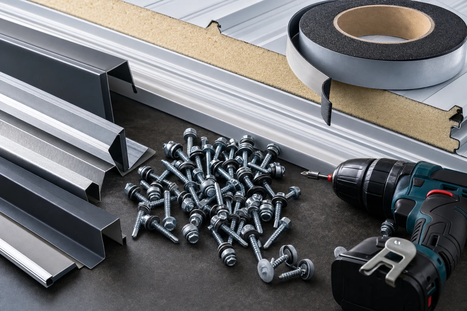
Flashing sections are joined with sealed laps — on the roof most often with butyl tape or compound, at terminations with neutral silicone, which does not react with the sheet coating. The flashing itself is fixed with short sheet metal fasteners or rivets — separate from the main fasteners that anchor the panel to the structure. We laid out this division of roles in the article on accessories and fixings for sandwich panels.
OB codes, or how to read the manufacturer’s catalogue
Every element in this article has its code in the Gór-Stal 2025 technical catalogue: from OB-01 (external corner) to OB-42 (starter C-profile). The catalogue contains 89 drawn installation junctions — each shows a cross-section of the detail with flashing codes and the type of gaskets and fasteners. Standard flashings are bent from the same coated sheet as the facings of the sandwich panels, so colour and coating match; non-standard ones are made to dimensions taken on site.
In practice it looks like this: you take the plan and sections of your building, find in the catalogue the junctions that occur in it — plinth, corners, eaves, gable, ridge, openings, possibly parapet and expansion joints — and write down the codes from them. This produces a complete list of flashings to order, in which nothing “comes out in the wash” on site. We know those 89 junctions inside out and go through this process with customers every day.
🤝 Contact a BOKKA technical advisor — send us the drawings of your building and we will help select the full set of flashings by OB code for your sandwich panel order.
Sources:
- Gór-Stal 2025 technical catalogue — installation junctions of GS insPIRe sandwich panels and the schedule of OB flashings
- PN-EN 14509 — Self-supporting double skin metal faced insulating panels — Factory made products — Specifications
- Technical data sheets of GS insPIRe S/U/D sandwich panels (Gór-Stal)
Frequently asked questions
What are flashings for on sandwich panel buildings?
What do the OB codes on the manufacturer’s drawings mean?
What does the ridge of a sandwich panel roof consist of?
In what order are flashings installed?
Do flashings have to come from the panel manufacturer?
Related products and systems
Read next
The most common sandwich panel installation mistakes — what to watch on site
Accessories and fixings for sandwich panels — a complete guide
Sandwich panel screws — how to match the length to panel thickness and substrate