PIR roof insulation — 6 mistakes that leave the U-value worse
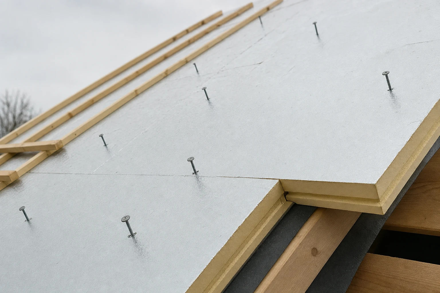
The design says it plainly: U = 0.15 W/(m²·K). Over-rafter roof, PIR boards, everything signed off. The first winter ends with a bill that agrees with nothing.
In February it snows. At the neighbour’s it lies for a week. At yours it is gone in three days, and parallel stripes of bare tile appear across the slope.
That is when the phone call goes to the supplier: “there’s something wrong with these boards”.
There is usually nothing wrong with the boards — λD = 0.022 W/(m·K) is a tested and declared value. The problem lies elsewhere: the design U-value describes the field of the element, while a building loses heat at edges, joints and penetrations. Six mistakes fit in there.
We are talking about rigid PIR insulation boards in roofs. Halls clad in sandwich panels have their own catalogue of installation slip-ups.
Mistake 1. A product chosen for its price, not for the job
The most expensive error happens before construction starts: somebody sees “PIR board, λ 0.022” in a price list and takes a single line item for the whole building.
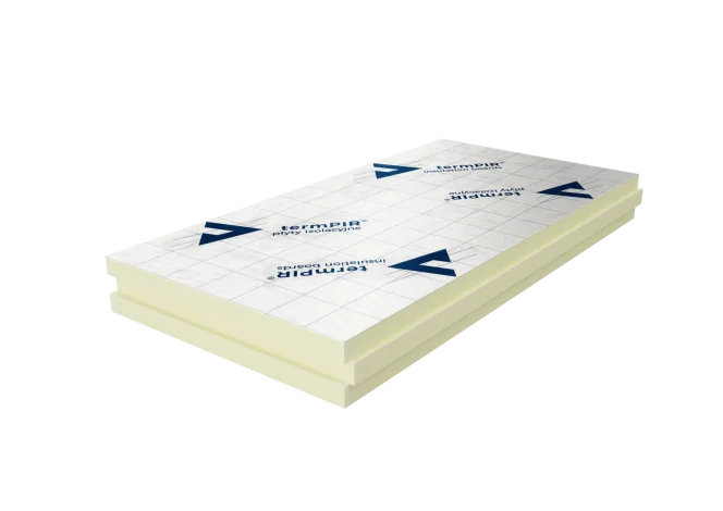
“PIR” is a family, not a product. A gas-tight aluminium–paper facing works well on a roof: it closes the core off against diffusion and acts as a barrier to vapour. Under thin-coat render the same board is a mistake, because ETICS needs an element that lets vapour through — the product for that is termPIR® ETX with a glass veil and assessment ETA 17/0066. termPIR® AL and MAX 19 AL are suitable neither for ETICS nor for washable ceilings or prefabrication.
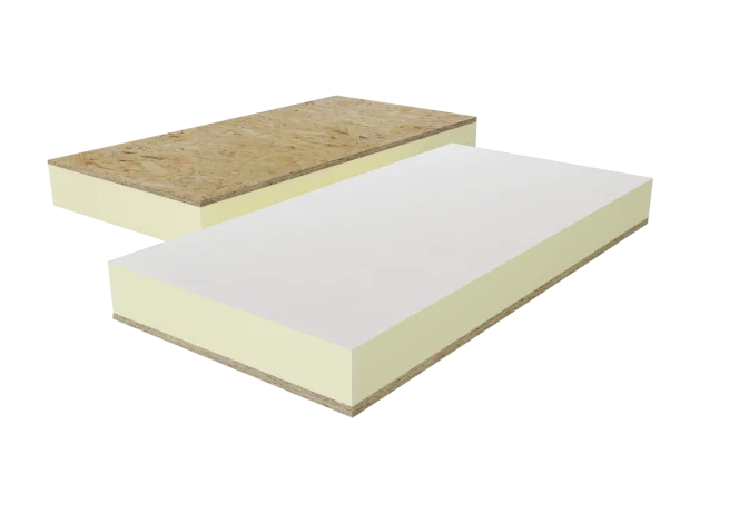
On a roof the mistake is a different one: a board with an aluminium facing needs a rigid substrate — boarding or OSB; with no decking you order the composite with factory-bonded OSB (a review of the methods). And a correction: the “aluminium” facing is aluminised paper of the order of 0.1 mm, not sheet metal. Swapping the covering for one other than the tested one, in turn, invalidates the fire classification (BROOF(t1) configurations).
Mistake 2. A hundred and forty instead of a hundred and fifty
Formally, this one is not a mistake at all. For termPIR® AL, a 140 mm layer above the rafters gives U ≈ 0.15 W/(m²·K) — exactly what the Technical Conditions require. The next commercial thickness, 150 mm, gives 0.14.
The difference is one centimetre of material. And the entire margin.
Because the U-value from the table applies to the field of the element: the boards and the rafters, nothing else. It does not include the screws, the cuts at a valley or the gap by the chimney. A hundred and forty lands on a boundary from which every detail pushes it onto the wrong side — which is why we say it plainly: aim for 150 mm. Where height is limited, the same effect comes from the variant with λD 0.019 — U ≤ 0.15 already at 130 mm (thickness tables).
Mistake 3. Screws, or how much steel sits in your roof
Count it with me. Counter-battens are fixed with screws passing through the whole insulation into the rafter — the manufacturer’s catalogue gives a spacing of about 40 cm, with one extra screw per linear metre at the edges. With rafters at 80–90 cm centres that works out at 3 screws per m² in the field and 4–6 in the edge zones.
With 150 mm of insulation each of them is about 300 mm of steel, which conducts heat more than two thousand times better than a PIR core. The effect: the fixings typically raise the U-value by 0.01–0.03 W/(m²·K) — with a design figure of 0.15, between 7 and 20 per cent, without a single workmanship error.
Hence the commonest temptation: to add screws “to be on the safe side”. That instinct is the opposite of what is needed — the spacing follows from wind load calculations to PN-EN 1991-1-4, and the denser pattern at the edges has an aerodynamic reason. What does help is a screw length matched to the board thickness (how to work it out) and two layers laid with staggered joints, so that the thermal bridges do not line up.
Mistake 4. Eight millimetres that cancel one per cent of the roof
On site this mistake does not even have a name. One board did not seat properly in the joint, the second was cut a touch short, the third was shoved home with a knee and sprang back. A gap is left.
Let us see what that means. A 1200 × 2400 mm board gives about 1.25 linear metres of joint for every square metre of roof — hence aluminium tape consumption of 1.25–1.5 m per m². If every joint has 8 mm of slack, that adds up to one per cent of the roof with no insulation. It sounds like nothing, but over that one per cent the U-value is not 0.15 but — counting cautiously — one and a half. The effective U-value of the slope lands around 0.165: ten per cent given away for free, in a place nobody will ever see.
What to do? Cuts made to measure, on a guide — a board forced in bends and springs back, opening the joint. Press the tongue-and-groove home along its whole length before the first screw goes in. Fill gaps with low-expansion foam, never high-expansion foam, which pushes the boards apart. Tape the joints: it looks like cosmetics, it is half the job.
Mistake 5. Eaves, ridge, chimney — where the design ends
In the design the element has one U-value and ends at the edge of the drawing. In the building it ends at the eaves, where it has to meet the wall insulation above the wall plate. If it does not meet it, a linear thermal bridge is born.
For a wall-to-pitched-roof junction the typical values with no design correction are Ψ = 0.15–0.40 W/(m·K). Take the middle of that range and a house with 35 metres of eaves and gables: 7 W/K escaping through the edge alone. The whole 150 m² slope at U = 0.15 loses 22.5 W/K. One badly resolved eaves detail adds as much as a third of the roof.
Everywhere the continuity of the layer breaks off works the same way: the chimney (the insulation has to reach the stack, not stop ten centimetres short), the access hatch and the roof window (the reveal needs insulating too), the ridge, the knee wall. The mechanism is the same as with thermal bridges at window junctions.
Mistake 6. Moisture and the order of layers, the fault that reports itself in winter
The previous five mistakes cost money. This one can cost you the structure.
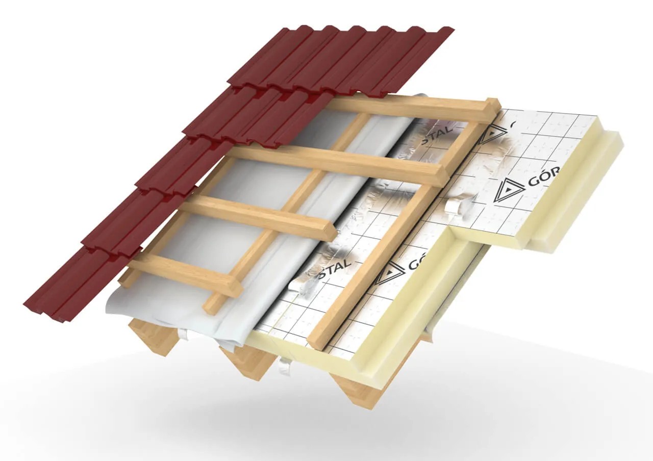
The order is short: vapour barrier on the warm side, PIR insulation, vapour-permeable underlay, a counter-batten giving a ventilation gap of at least 2.5 cm, a tile batten, the covering. The role of the vapour barrier is sometimes taken over by the board’s gas-tight facing — but only with taped joints and sealed penetrations.
The rest of the slip-ups are mundane. The underlay beneath the boards instead of above them. A counter-batten with no gap, so nothing ventilates. Installation onto soaked boarding — water shut in under a gas-tight layer has no way out. A pallet of boards left uncovered on site for a week.
The consequence is delayed and therefore misleading: the first frost chills the cold side of the element below the dew point, vapour condenses where it should not, and after a few weeks dark patches appear on the sloping ceilings. The owner reports “a leaking roof” and is wrong — we described the mechanism separately.
| Mistake | What happens | How to prevent it |
|---|---|---|
| Wrong board variant | The product does not work in the system | For ETICS only ETX; on a roof, a rigid substrate |
| Thickness “by eye” | 140 mm with no margin for bridges | 150 mm or the λD 0.019 variant |
| Bridges at the fixings | U up by 0.01–0.03 W/(m²·K) | Spacing from calculations, layers staggered |
| Gaps at the joints | 8 mm of slack = 1% of the roof uninsulated | Cuts to measure, joint pressed home, tape |
| Broken continuity | Linear bridge Ψ 0.15–0.40 W/(m·K) | The detail from the design, insulated reveals |
| Moisture and the wrong order | Condensation, damp timber | Taped vapour barrier, underlay on top |
How to check whether your roof has any of these faults
The cheapest diagnostic tool is free and needs only frost and snow. An even layer that lies for a long time is a good sign. Stripes of melted snow along the counter-battens point to thermal bridges at the fixings; patches by the chimney and the eaves point to broken insulation. Icicles have a story of their own: heat melts the snow higher up, the water runs down onto the cold eaves and freezes.
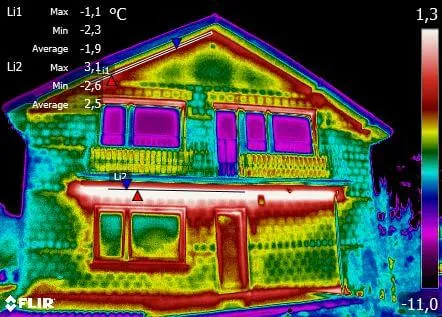
The second step is a thermal imaging survey — it needs a temperature difference of at least 15 K, no sun and no wind, so the realistic window is November to March. The third piece of evidence is the bill set against the design energy performance: a discrepancy of ten or twenty per cent is within the variation in how people live, a twofold one is not.
Six mistakes, one rule
None of the six is spectacular — each takes a few per cent and each, on its own, can be shrugged off. Only together do they turn a design U-value of 0.15 into a building performing like 0.19: a quarter more heat escaping through the roof, for every winter of that roof’s life.
The common denominator: the U-value from the design describes the field of the element, while the bill is decided by edges, joints and penetrations. A PIR board gives you the lowest lambda and the thinnest layer. The one thing it will not do is stand in for the contractor at the eaves detail.
🤝 Contact a BOKKA technical advisor — we will select the variant and thickness of termPIR® boards for your roof build-up and point you to the eaves, ridge and penetration details before the crew gets onto the slope.
Sources:
- Technical catalogue for termPIR® boards — residential buildings: over-rafter roof (screw spacing and length)
- Technical data sheet for termPIR® AL — λD 0.022 W/(m·K), Al/paper/PE facing
- PN-EN ISO 10211 — Thermal bridges in building construction
- PN-EN 13187 — Qualitative detection of thermal irregularities in building envelopes
- Technical Conditions (WT 2021), Annex 2 — thermal insulation of building elements
Frequently asked questions
Can a badly insulated roof be improved without stripping it?
How much heat escapes through the screws fixing the counter-battens?
Is a vapour barrier needed under PIR boards on a roof?
Can PIR boards be laid over an existing layer of insulation?
Related products and systems
Read next
Thermal Bridges — How to Eliminate Them with PIR Boards (WT 2021)
Attic Insulation Thickness per WT 2021 — PIR Boards | BOKKA
Over-Rafter Roof Insulation with PIR Boards — Complete Guide
