Why this detail is critical
The plinth is the most difficult detail in cold room / freezer construction. Here is what can go wrong:
- Thermal bridge at floor level — without perimeter termPIR® insulation, the chamber floor slab is in direct contact with the external foundation. The bridge can cause a local temperature drop in the chamber of 2–3°C and condensation on the floor outside the chamber.
- Ground freezing under the chamber — in freezers (–30°C) without perimeter insulation, the ground freezes outside the chamber outline, in extreme cases causing floor heave.
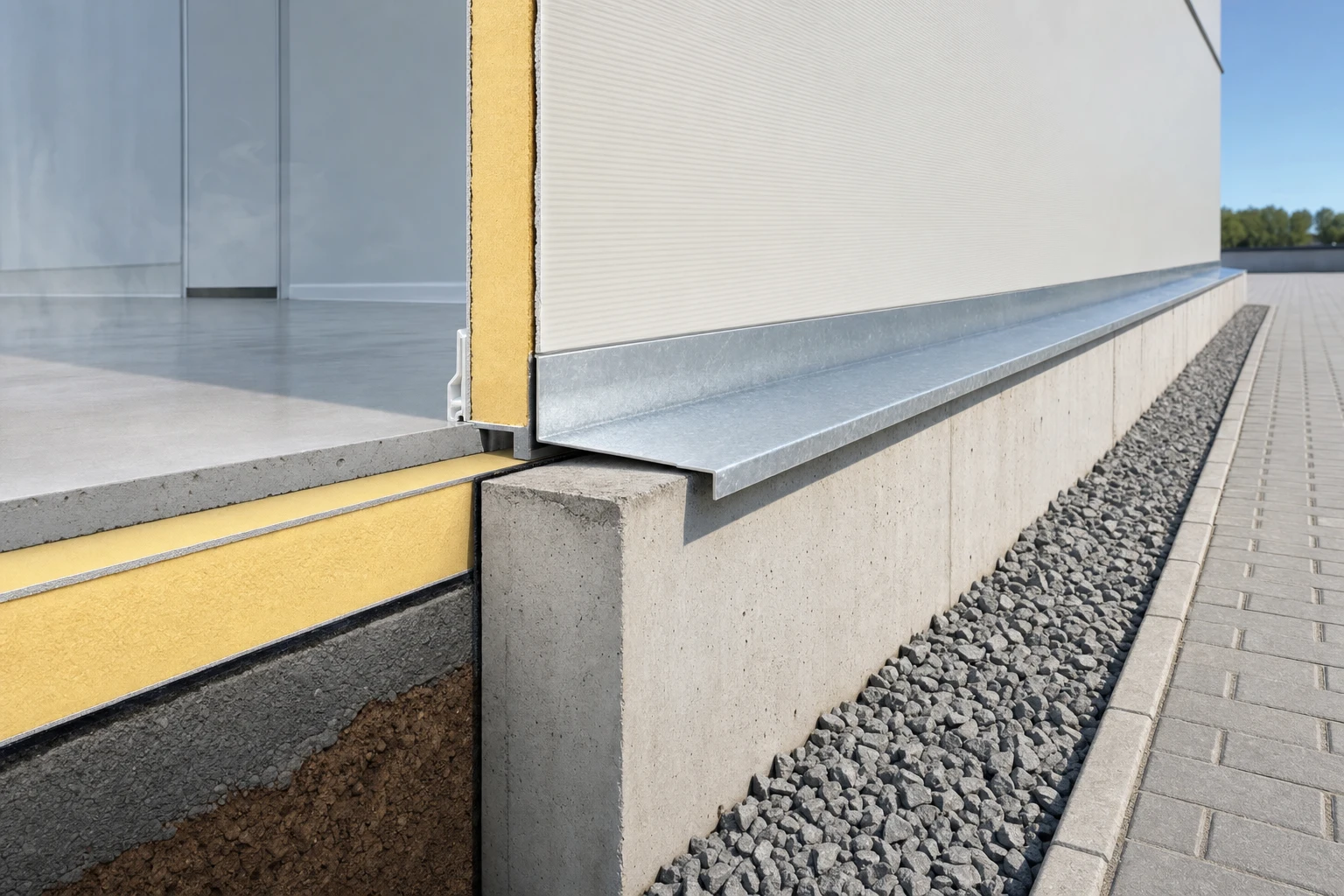
- Rainwater ingress behind the plinth — without flashing with a slope, water running off the façade penetrates behind the insulation, causing corrosion of the sandwich panels.
What this system solves
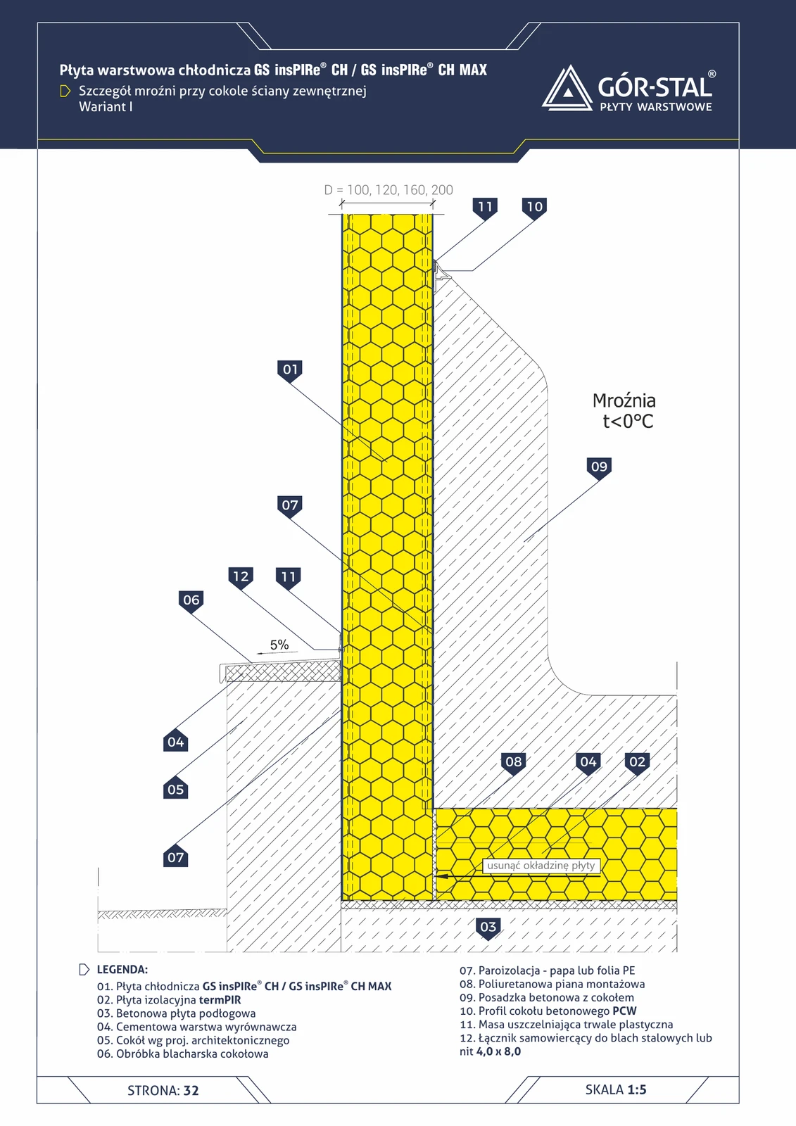
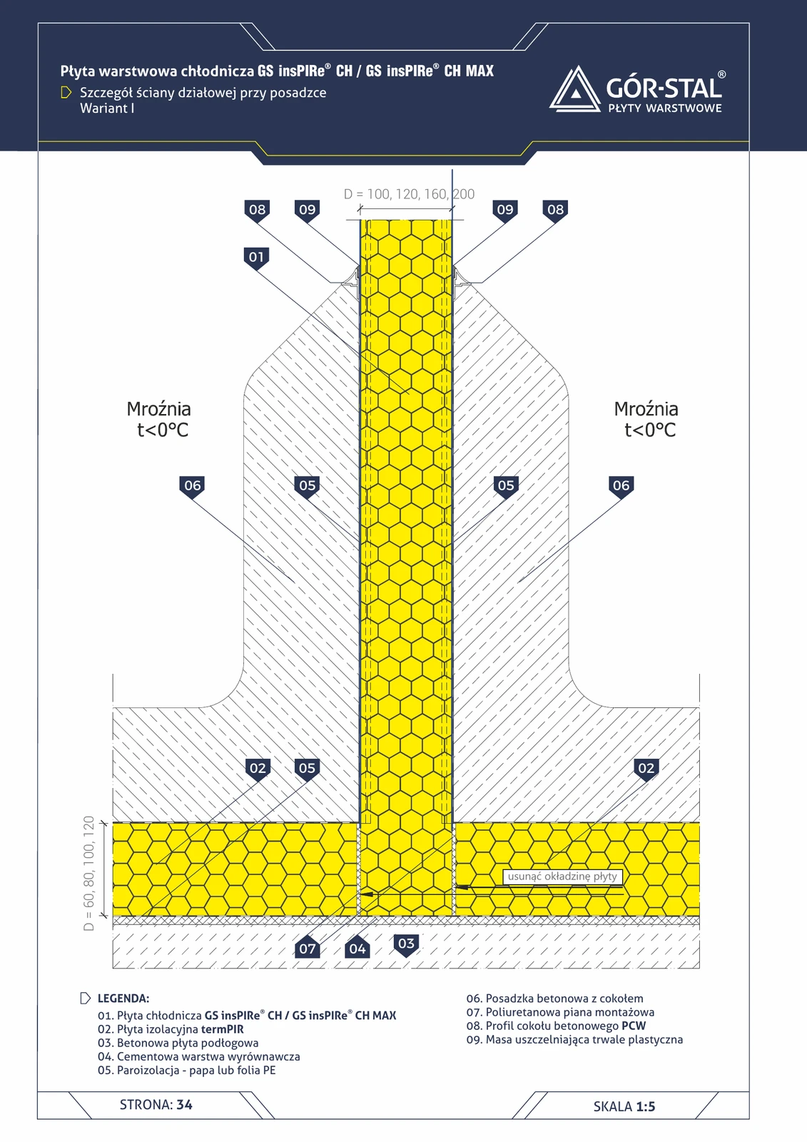
- Thermal bridge interruption — a 80–120 mm termPIR® AL strip laid around the perimeter beneath the floor, across the full thickness of the chamber slab + 30 cm beyond the outline.
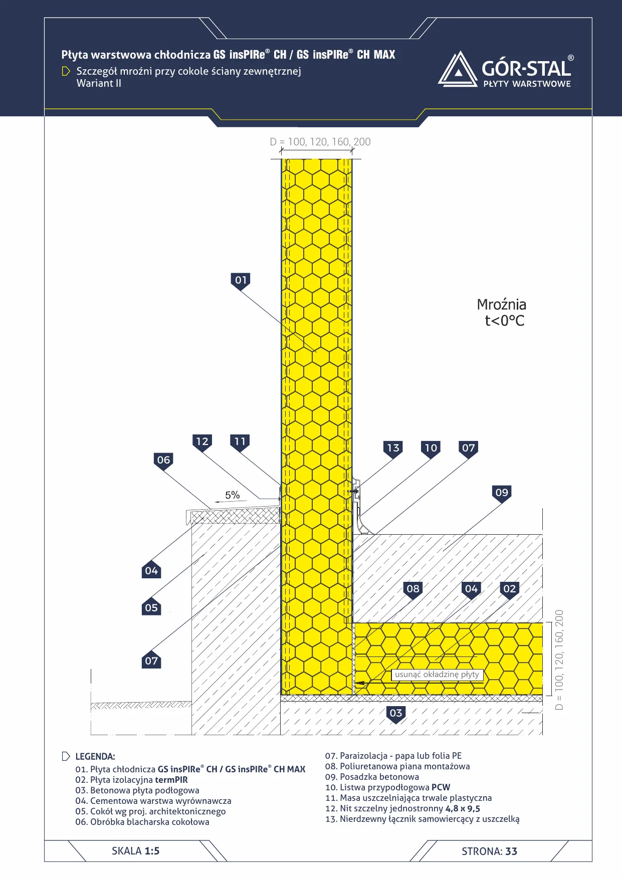
- Plinth waterproofing — plinth flashing with a 5% slope directs water beyond the cold room outline.
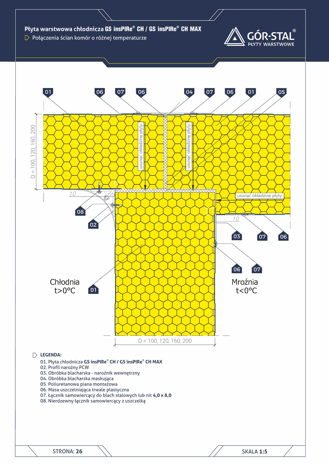
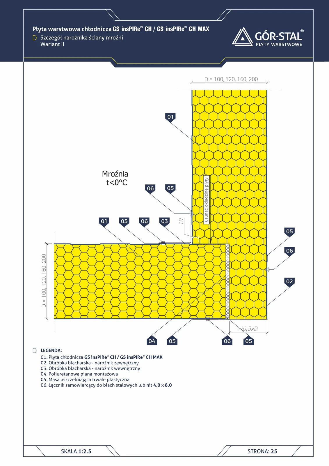
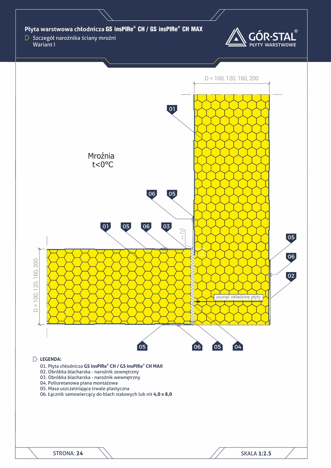
- Internal finish — a PVC plinth profile in place of a metal-to-metal joint eliminates the bridge at the floor–chamber wall junction.
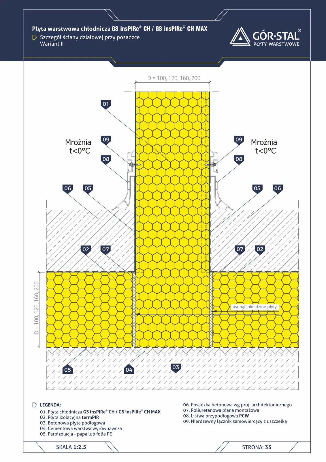
Variant I vs Variant II
The manufacturer’s catalogue describes two variants:
- Variant I (this system) — floor-level perimeter insulation (termPIR® below the floor) + external plinth flashing. Standard for new buildings.
- Variant II — vertical perimeter insulation (termPIR® as a strip around the chamber wall on the outside). Used in refurbishments where the existing floor cannot be disturbed.
Installation requirements
- Perimeter termPIR® laid before the chamber floor screed is poured; vapour-barrier joints to be sealed with butyl tape.
- Plinth flashing mechanically fixed to the sandwich-panel wall + EPDM gasket on the external side.
- 5% slope absolutely required — lower → water does not drain, higher → poor appearance.
- PVC plinth profile sealed with frost-resistant silicone (Sika SikaSil-G+) on the cold room side.
Required flashings
- OB-13 — plinth drip flashing (variants: wide / narrow / stiffened)
- OB-14 — small plinth drip flashing (for low plinths)
- OB-15 — stiffened plinth drip flashing (for exposed walls)
- OB-36 — panel closing flashing (at the floor junction)
Technical documentation
Cold Storage Catalogue 2025 (Gór-Stal, 2025-04-23, p. 32). The detail is described in the “Cold room and freezer plinths” section together with sectional drawings and a component list.
Layer composition
| # | Layer | Thickness | λ | Role |
|---|---|---|---|---|
| 1 | insPIRe® CH / CH MAX cold storage panel (vertical) | 100–200 mm | 0,022 W/(m·K) | cold room wall (sandwich panel) |
| 2 | termPIR® AL (perimeter insulation below the floor) | 80–120 mm | 0,022 W/(m·K) | plinth / foundation insulation (thermal bridge break) |
| 3 | Vapour barrier — bituminous felt or PE film | — | — | vapour barrier |
| 4 | Cement levelling layer | — | — | levelling |
| 5 | Concrete floor slab | — | — | floor structure |
| 6 | Concrete floor finish with skirting | — | — | wearing layer |
| 7 | Plinth flashing (5% slope) | — | — | water-drainage slope |
| 8 | PVC concrete plinth profile | — | — | internal plinth finish inside the chamber |
Related catalogue items
Applications
Installation accessories